Freightliner FLA/FLB/FLC/FLD/FLL. Manual - part 20


  Index      Freightliner     Freightliner FLA/FLB/FLC/FLD/FLL - service manual 2009 year


Search            


Content   ..  18  19  20  21   ..


Freightliner FLA/FLB/FLC/FLD/FLL. Manual - part 20


4.

Inspect the housing weldment for cracks,
warpage, or damage. If cracks are found, replace
the component.

5.

Inspect the operating rod for cracks, warpage, or
damage. If cracks are found, replace the compo-
nent.

6.

Check the safety indicator for proper function.
When the air mechanism unit is activated, the
operating rod is forced into the lockset position
and the safety latch will rotate toward the rear.

7.

Check the exhaust seat and inlet valve seat for
nicks or burrs. Inspect all rubber parts for signs
of cuts, abrasion, swelling, or deterioration. Re-
place as necessary.

ASF Touchloc

Control Mechanism

System Operation Check

1.

Park the vehicle and chock the tires.

2.

With the parking brake not set, pull the
Touchloc control valve. The air cylinder should
not activate 
the air mechanism unit.

If the air cylinder is activated, check the
inversion and the cab control valves for
proper operation.

Replace malfunctioning valves.

After replacing the valves, recheck for
proper system operation.

3.

With the parking brake set, determine that the
brakes have been applied. Pull the Touchloc con-
trol valve. The air cylinder should activate the
air mechanism unit.

If the air cylinder does not function, check
the inversion and cab control valves for
proper operation.

Replace the malfunctioning valves.

After replacing the valves, recheck for
proper system operation.

NOTE: Neither the vehicle nor the air mecha-
nism system should be operated when the
spring brake section is caged.

4.

Remove the chocks from the tires.

31–02 Fifth Wheel Lubricating

To maintain proper fifth wheel operation, always lubri-
cate the fifth wheel after an inspection has been
performed.

IMPORTANT: Lubricate the fifth wheel:

After power washing, or steam cleaning.

If the vehicle operates in harsh conditions such
as salt spray from road surfaces, or in ex-
tremely dusty environments.

After any service that requires the removal of
lubrication from the fifth wheel head or compo-
nents.

WARNING

Failure to properly lubricate the fifth wheel could
result in a possible disengagement of the trailer
from the tractor, which could result in personal
injury or property damage.

Fontaine

Use a multipurpose extreme pressure (EP) chassis
grease, and lubricate all moving parts on the fifth
wheel. When lubricating the top plate at the grease
fittings for the bracket bearing area, tilt the top plate
forward and backward to evenly distribute the
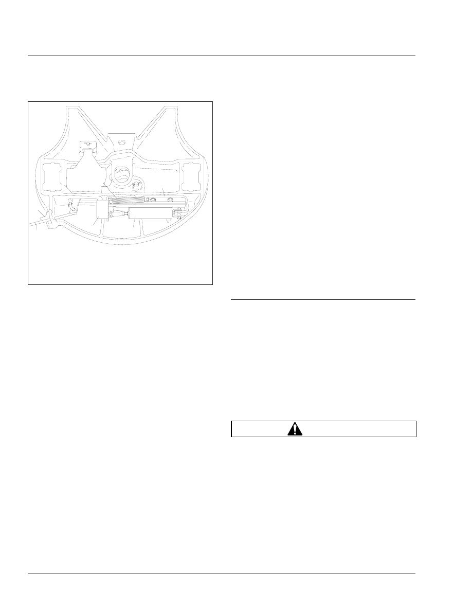
f310550

09/12/96

1

2

3

4

5

6

1.

Air Cylinder

2.

Slide Cam and
Housing

3.

Return Spring

4.

Housing Weldment

5.

Operating Rod

6.

Safety Indicator

Fig. 8, Touchloc Control Mechanism Component

Inspection

Frame and Fifth Wheel

31

31/6

grease. Using a pry tool, separate the jaw and
wedge and lubricate the serrations using a brush to
distribute the grease. On slide-mount applications,
lubricate the slide rail and tapered wedges for
smooth operation.

Once the moving parts of the fifth wheel are lubri-
cated, apply a liberal coating of grease to the top
plate and the trailer kingpin plate.

Holland

Lubricate all moving parts with a multipurpose chas-
sis grease. Lubricate, with a multipurpose chassis
grease, the two grease fittings located on either side
of the top plate.

Once the fifth wheel’s moving parts are lubricated,
apply a heavy coat of grease to the top plate by di-
rect application. On slide-mount applications, lubri-
cate the baseplate rails and the plungers for smooth
operation.

Castloc II and Simplex Series

Use a chassis or multipurpose grease to lubricate the
two grease fittings located on either side of the fifth
wheel top plate. Lubricate the two grease fittings lo-
cated in the grease grooves on the fifth wheel top
plate. Lubricate the two grease fittings located below
the top plate mounting pins. Lubricate the lock
mechanism.

Once the fifth wheel’s moving parts are lubricated,
apply a heavy coat of grease to the top plate, either
through the grease fittings located on the underside
of the top plate, or by direct application. On slide-
mount applications, lubricate the slider lock pockets
and the slider bracket.

31–03 Frame Fastener Torque

Checking

Frame brackets and components secured with Huck-
bolt

®

fasteners do not require a torque check, how-

ever, they should be inspected for damage. Frame
brackets and components secured with conventional
bolts and nuts are to be checked at initial mainte-
nance (IM). Check the torque of frame fasteners to
offset the effects of "bedding in" (or seating). When
checking torque, torque the nut, not the bolt head
whenever possible. This will give a true torque read-
ing by eliminating bolt body friction. When checking

the torque of frame fasteners, inspect the frame for
cracks and other damage. Set a click-type torque
wrench to the maximum torque of the fastener you
are checking. Apply pressure until the torque wrench
clicks. Do not loosen the bolt to check the torque.
See the applicable torque table in

Group 00

for

torque specifications.

CAUTION

Make sure frame fasteners are properly tightened.
Continued vehicle operation with loose fasteners
could result in bracket or frame damage.

NOTE: Engine supports on vehicles built from
January 2007 do not require checking.

Inspect, and check the torque of the fasteners at
these locations:

Axle Stops

Deck Plates

Engine Trunnion Supports

Equalizer Brackets

Exhaust Brackets

Fifth Wheel Legs

Fifth Wheel Mountings

Frame Crossmembers and Gussets

Front Frame Brackets

Front Suspension Spring Brackets

Fuel Tank Brackets

Radius Rods

Rear Engine Supports

Rear Suspension Spring Brackets

Shock Absorbers

All Other Frame Fasteners

Any component that shows signs of cracking or other
damage, must be repaired or replaced. Refer to the

Heavy-Duty Trucks Service Manual

for repair or re-

placement information in the respective section for
the component in question.

Frame and Fifth Wheel

31

31/7

31–04 Holland Fifth Wheel

Sliding Mechanism
Inspecting

1.

Loosen the locking plunger jam nut and turn the
adjusting bolt out (counterclockwise). See

Fig. 9

.

2.

Disengage and engage the locking plungers.
Check that the plungers are securely seated
without binding. If the locking plungers do not
operate properly, see Group 31 of the

Heavy-

Duty Trucks Service Manual

for adjustment pro-

cedures.

3.

Turn the adjusting bolt in (clockwise) until it con-
tacts the rack. Turn the adjusting bolt an addi-
tional 1/2 turn, then securely tighten the locking
nut.

31–05 Trailer Electrical

Connector Lubricating

In some cases, failure of trailer cables occurs due to
intrusion of chloride-based road deicing chemicals
into the trailer connector. Once inside the connector,
the chloride-based chemicals corrode the brass ter-
minals and create bridging between positive and
ground terminals.

NOTE: The use of soap is not recommended for
cleaning the electrical connector, as some
soaps may increase the corrosion process.

1.

Wash out any existing grease, dirt, and corrosion
on the trailer connectors with electrical contact
cleaner spray.

2.

Grease the trailer connector with a lithium-based
dielectric grease.

f310371

1

2

3

4

11/21/95

1.

Rack

2.

Plunger

3.

Pocket

4.

Plunger Adjusting Bolt

Fig. 9, Locking Plungers

Frame and Fifth Wheel

31

31/8

Title of Maintenance Operation (MOP)

MOP Number

Suspension Inspecting . . . . . . . . . . . . . . . . . . . . . . . . . . . . . . . . . . . . . . . . . . . . . . . . . . . . . . . . . . . . . . 32–01

Suspension Lubricating. . . . . . . . . . . . . . . . . . . . . . . . . . . . . . . . . . . . . . . . . . . . . . . . . . . . . . . . . . . . . . 32–02

Suspension U-Bolt Torque Checking . . . . . . . . . . . . . . . . . . . . . . . . . . . . . . . . . . . . . . . . . . . . . . . . . . . . 32–03

Suspension

32

Index, Alphabetical


Content   ..  18  19  20  21   ..