Freightliner FLA/FLB/FLC/FLD/FLL. Manual - part 19


  Index      Freightliner     Freightliner FLA/FLB/FLC/FLD/FLL - service manual 2009 year


Search            


Content   ..  17  18  19  20   ..


Freightliner FLA/FLB/FLC/FLD/FLL. Manual - part 19


7.3

Install the fifth wheel top plate, bushing
pins, and roll pins.

8.

Inspect for fatigue or cracked welds.

9.

Replace cracked, worn, or damaged parts with
new parts. Replace all loose mounting bolts with
5/8–11 SAE grade 8 bolts, grade C locknuts, and
hardened washers.

Do not

re-use bolts, nuts,

and washers on fifth wheel mountings.

10. After inspecting the fifth wheel, lubricate all mov-

ing parts with a chassis or multipurpose grease.
See

Maintenance Operation 31–02

for lubrica-

tion instructions.

Castloc II and Simplex Series

1.

Disconnect the tractor from the trailer. For in-
structions, see the vehicle driver’s manual.

2.

Thoroughly steam clean the fifth wheel.

3.

Check the fifth wheel plate for cracks. Check for
sharp edges on top; the chamfer should be 1/8
to 1/4 inch (3 to 6 mm).

4.

When the wheel is locked, the safety latch must
swing free and fall freely into position. See
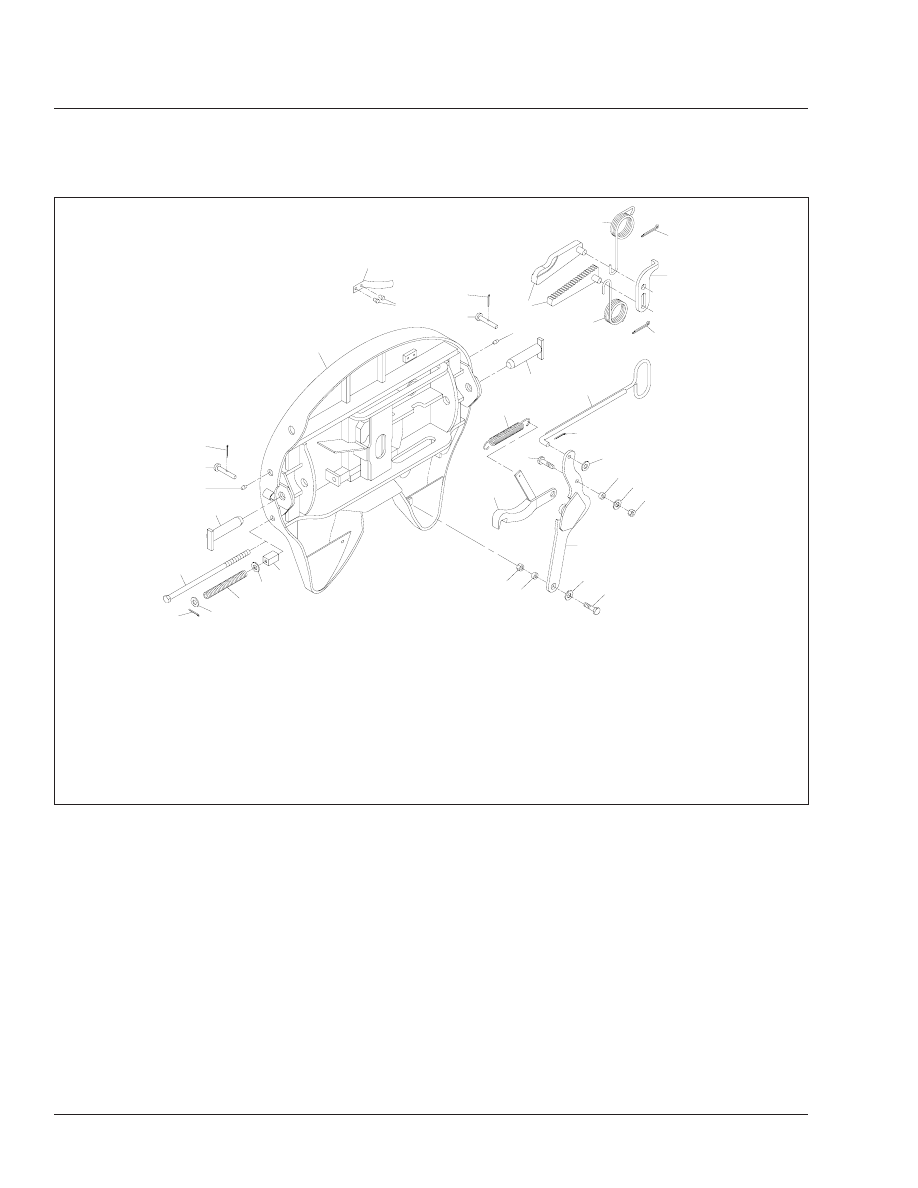
Fig. 3

.

f310476

09/18/95

1

2

3

4

5

6

7

6

8

1

9

10

11

12

3

4

1

2

18

13

14

15

14

16

17

1

21

21

21

22

23

23

24

25

26

20

19

1.

3/16 x 1 Cotter Pin

2.

Lower Bracket Retainer Pin

3.

Grease Fitting

4.

Lower Bracket Pin

5.

Wedge Stop Rod

6.

Flatwasher

7.

Wedge Stop Rod Spring

8.

Wedge Stop Rod Nut

9.

Side Release Upper Assembly

10. Leaf Spring

11. 1/4–20 x 3/8 Thread-Cutting

Screw

12. Step Jaw and Wedge
13. Jaw Spring
14. 1/4 x 3 Cotter Pin
15. Timer
16. Wedge Spring
17. Pull Handle
18. Bumper Handle Spring

19. 1/2–13 x 2 Bumper Pivot Bolt
20. Bumper
21. Flatwasher
22. 5/16" Bumper Pivot Bushing
23. 1/2–13 Locknut
24. 7/16" Handle Pivot Bushing
25. Operating Handle (side-release

only)

26. 1/2–13 x 2 Handle Pivot Bolt

Fig. 1, Fontaine H5092 Series Fifth Wheel (left-side-release shown)

Frame and Fifth Wheel

31

31/2

5.

The lever bar and operating handle must be in
proper alignment. See

Fig. 4

Compare the lever

bar and operating handle alignment to a new, or
a properly operating lever bar and operating
handle. Replace any bent or misaligned lever bar
or operating rod.

6.

Check all cotter pins for cracking or damage. Re-
place any cotter pin that shows any signs of
damage.

7.

Level the fifth wheel plate to a horizontal posi-
tion. Measure the height from a stationary
mounting point (see

Fig. 5

Ref. 3), such as the

08/29/95

f310472

12

11

13

1

2

3

4

5

6

10

8

9

18

17

15

7

16

15

14

14

13

1.

Locknut, 3/4–16

2.

Washer

3.

Rubber Washer

4.

Lock Adjustment Tag

5.

Yoke Shaft

6.

Yoke Sub-Assembly

7.

Torsion Spring

8.

Roll Pin

9.

Secondary Lock, Right-Hand

10. Cam Plate
11. Lock Guard
12. Pin

13. Lock Pin
14. Lock Jaw
15. Washer
16. Right-Hand Release Handle
17. Left-Hand Release Handle
18. Secondary Lock, Left-Hand

Fig. 2, Holland Fifth Wheel

Frame and Fifth Wheel

31

31/3

frame rail to the top of the fifth wheel plate (Ref.
1). Pry up on the fifth wheel plate (Ref. 4) below
the pin boss, and measure the vertical move-
ment (Ref. 5). The bracket connection provides a
9/32-inch (7-mm) vertical clearance to provide
cushioning and to avoid downward pin-loading
while retaining minimum plate lift. If the plate lift
(Ref. A) exceeds 5/16 inch (8 mm) as a result of
wear or rubber deterioration, install new, stan-
dard or oversized bracket-shoe rubber pads; see
Group 31 of the

Heavy-Duty Trucks Service

Manual

for replacement instructions.

NOTE: Do not measure plate lift immediately
after a trailer has been uncoupled from the fifth
wheel. The rubber may have taken a temporary
set, which will normally recover after being un-
coupled for a short period of time.

8.

Check all mounting bolts for signs of fatigue, and
tighten them to the proper torque. For torque
specifications, see

Group 00

of this manual. In-

spect all angles, plates, and brackets for cracks
or other damage.

9.

Replace cracked, worn, or damaged parts with
new parts. Replace all loose mounting bolts with
5/8–11 SAE grade 8 bolts, grade C locknuts, and
hardened washers.

Do not

re-use bolts, nuts,

and washers on fifth wheel mountings.

10. After inspecting the fifth wheel, lubricate all mov-

ing parts with a chassis or multipurpose grease.
See

Maintenance Operation 31–02

for lubrica-

tion instructions.

ASF Touchloc

Control Mechanism

General Inspection

1.

Replace cracked, broken, bent, or missing parts
with new parts. See

Fig. 6

.

2.

The cotter pin located in the slide cam clevis pin
must be in place and properly spread.

f310353b

1

2

3

4

11/28/95

1.

Lubricant Grooves

2.

Safety Latch

3.

Lock Control Handle

4.

Mount

Fig. 3, Simplex Series Fifth Wheel

09/15/95

f310470

1

2

1.

Operating Handle

2.

Lever Bar

Fig. 4, Lever Bar and Operating Handle Alignment

f310475

08/31/95

1

2

3

A

4

5

A. Extended Top Plate Lift Height
1.

Fifth Wheel Top Plate

2.

Fifth Wheel Frame Mount

3.

Frame Rail

4.

Lifting Point

5.

Static Top Plate Height

Fig. 5, Measuring Fifth Wheel Top Plate Lift

Frame and Fifth Wheel

31

31/4

3.

The locknut that attaches the air cylinder to the
housing weldment must be tight, but should not
distort the cylinder clevis legs inward.

4.

Check all mounting bolts for tightness.

NOTE: A sluggish slide cam may be improved
by spraying the slide cam, track, and inside of
the rectangular slide cam housing with a prod-
uct such as light oil, silicon lube, or equivalent.

ASF Touchloc

Control Mechanism

Lubrication

1.

With the air cylinder and the slide cam in the re-
tracted position, lubricate the cam track with a
light oil-type lubricant. See

Fig. 7

.

2.

If the operating rod plate casting track is rusted,
apply penetrating oil (with teflon) to remove the
rust. Apply white lithium grease into the track.

3.

Remove the extension spring for easy access.

4.

Activate the cab control valve, moving the oper-
ating rod into lockset (unlocked mode) position.

5.

Lubricate the slide cam shaft.

6.

Spray lubricant into the rectangular slide cam
housing.

7.

Replace the extension spring.

8.

Cycle the slide cam several times to ensure
smooth operation.

9.

Lubricate the air mechanism unit each time the
tractor is steam cleaned.

ASF Touchloc

Control Mechanism

Component Inspections

1.

Thoroughly inspect the air cylinder (

Fig. 8

). It

must retract and extend throughout the operating
range without any interruption of piston travel.

The air cylinder is in satisfactory working order
upon completion of six consecutive extensions
and retractions at 90 to 120 psi standard operat-
ing pressure.

If the air cylinder does not function properly, re-
move the air cylinder. Manually extend the piston
to its maximum length, and retract fully. Any bind-
ing of the piston requires reconditioning or
replacement.

2.

Inspect the slide cam and housing for any
warpage, damage, or cracks. If any cracks are
found, replace the components.

3.

Check the return spring for overextension, abra-
sion, and a rust-deteriorating condition which
would require replacement.

f310549

1

2

3

4

09/12/96

1.

Cotter Pin

2.

Locknut

3.

Mounting Bolts

4.

Slide Cam

Fig. 6, Touchloc Control Mechanism General Inspection

f310548

1

10/17/96

1.

Extension Spring

Fig. 7, Touchloc Control Mechanism Lubrication

Frame and Fifth Wheel

31

31/5


Content   ..  17  18  19  20   ..