Freightliner FLA/FLB/FLC/FLD/FLL. Manual - part 23
Hendrickson RT2 and RTE2 Series
1.
Park the vehicle on a level surface, apply the
parking brakes, and chock the front tires.
Raise the rear of the vehicle until the rear wheels
are suspended in the air, then support the ve-
hicle with safety stands.
2.
Check the torque of the number-one spring
hanger (double-lock-bolt design) lock bolt nuts. If
a loose connection has caused pin hole wear,
replace the hanger.
3.
Inspect the pin hole in the outboard leg of the
number one spring hanger (draw-key design) for
wear or elongation.
WARNING
Wear at this point requires hanger replacement, or
premature fracture of the spring hanger pin may
occur, with possible separation of components
and loss of vehicle control. This could result in
serious personal injury or property damage.
4.
Visually inspect the cam surface of the number-
two spring hanger for wear due to operating
mileage. Also, inspect the outside legs for wear
which can be caused by worn spring eye bush-
ings.
NOTE: RTE2 (extended-leaf-spring) suspen-
sions require a minimum gap of 3/8 inch (9.5
mm) between the cam surface of the number-
two spring hanger and the top of the main leaf
in the unloaded condition. See
. If this
gap is less than 3/8 inch (9.5 mm), the
extended-leaf portion of the spring will not per-
form satisfactorily for an empty ride.
5.
Inspect the cam surface on the number-three
spring hanger (extended-leaf-springs only) for
wear. Excessive wear will reduce the gap avail-
able at the number-two spring hanger. Refer to
the previous note.
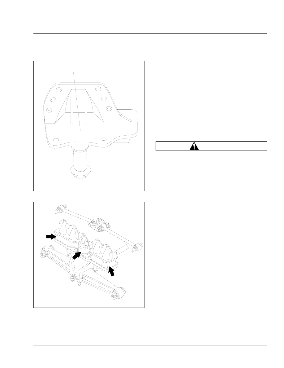
6.
Place a block of wood on the leaf spring. See
. Place a pry bar on the block of wood
and insert the end of the pry bar under the frame
hanger. Attempt to lift the frame hanger, as
shown in
. Also, with an empty chassis
and the brakes applied, attempt to rock the chas-
sis back and forth while observing the spring
eye. In either case, if 1/8 inch or more of move-
09/15/95
f320421
1
1.
Rust Inspection Area
Fig. 16, Hendrickson RS Series Rust Inspection
f320318a
05/27/93
Fig. 17, Hendrickson RS Series Load Cushion
Inspection
Suspension
32
32/9