Ford Galaxy / Ford S-MAX. Manual - part 809
 

  Index      Ford     Ford Galaxy / Ford S-MAX - service repair manual 2006 year


Search            


Content   ..  807  808  809  810   ..


Ford Galaxy / Ford S-MAX. Manual - part 809


system touch screen and soldered connection SP196 
using the Wiring Diagrams. CHECK the operation of 
the system. 
- If a resistance of more than 2 Ohms is measured in 
both of the measurements:LOCATE and RECTIFY the 
open circuit in the circuit between soldered 
connection SP196 and ground connection G6D139 
with the aid of the Wiring Diagrams. CHECK the 
operation of the system. 

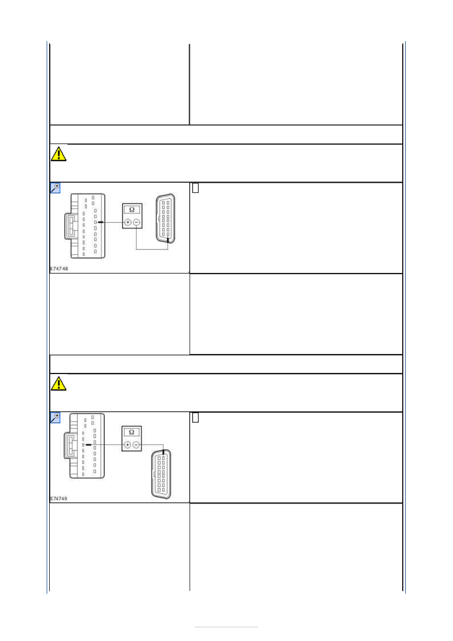
G8: CHECK FOR OPEN CIRCUIT BETWEEN THE NAVIGATION SYSTEM TOUCH SCREEN 
AND THE DATA LINK CONNECTOR (DLC)

CAUTION: The following measurement must only be performed using the Ford 

approved diagnostic tool digital multimeter. Failure to observe this instruction can lead to 
damage. 

Measure the resistance between the navigation 
system touch screen, connector C2ME03-F, pin 15, 

circuit VDB14G (VT/GY), wiring harness side and the 
DLC, connector C3DB04, pin 8, circuit VDB14F 
(VT/GY), wiring harness side. 

Is a resistance of less than 2 Ohms registered? 
Yes 

GO to G9

.  

No 

LOCATE and RECTIFY the break in circuit VDB14G 
(VT/GY) between the navigation system touch screen 
and soldered connection SP350 with the aid of the 
Wiring Diagrams. CHECK the operation of the 
system. 

G9: CHECK FOR OPEN CIRCUIT BETWEEN THE NAVIGATION SYSTEM TOUCH SCREEN 
AND THE DLC

CAUTION: The following measurement must only be performed using the Ford 

approved diagnostic tool digital multimeter. Failure to observe this instruction can lead to 
damage. 

Measure the resistance between the navigation 
system touch screen, connector C2ME03-F, pin 5, 

circuit VDB13H (BU/GY), wiring harness side and the 
DLC, connector C3DB04, pin 1, circuit VDB13F 
(BU/GY), wiring harness side. 

Is a resistance of less than 2 Ohms registered? 
Yes 

CHECK and if necessary RENEW the navigation 
system touch screen. CHECK the operation of the 
system. 

No 

LOCATE and RECTIFY the break in circuit VDB13H 
(BU/GY) between the navigation system touch screen 
and soldered connection SP345 with the aid of the 


Wiring Diagrams. CHECK the operation of the 
system. 

PINPOINT TEST H : DVD DRIVE NOT COMMUNICATING WITH THE FORD 
APPROVED DIAGNOSTIC TOOL - VEHICLES EQUIPPED WITH DVD 
NAVIGATION SYSTEM WITH TOUCH SCREEN 

TEST CONDITIONS

DETAILS/RESULTS/ACTIONS

H1: CHECK COMMUNICATION WITH THE INSTRUMENT CLUSTER

Ignition switch in position 0. 

Connect the diagnostic tool. 

Select the instrument cluster with the Ford 
approved diagnostic tool. 

Is it possible to establish communication with the 
instrument cluster? 
Yes 

GO to H2

.  

No 

GO to Pinpoint Test 

AH. 


H2: CHECK FUSE F6

Ignition switch in position 0. 

CHECK Fuse F6 (CJB). 

Is the fuse OK? 
Yes 

GO to H3

.  

No 

RENEW fuse F6 (15 A). CHECK the operation of the 
system. If the fuse blows again, LOCATE and 
REPAIR the short using the Wiring Diagrams. 

H3: CHECK THE VOLTAGE AT FUSE F6

Connect Fuse F6 (CJB). 

Measure the voltage between fuse F6 (15 A) and 
ground. 

Does the meter display battery voltage? 
Yes 

GO to H4

.  

No 

REPAIR the voltage supply to fuse F6 with the aid of 
the Wiring Diagrams. CHECK the operation of the 
system. 

H4: CHECK THE VOLTAGE AT THE DVD DRIVE

Disconnect Connector C2ME04 from the DVD drive. 

Measure the voltage between the DVD drive, 
connector C2ME04, pin 1, circuit SBP06F (BN/RD), 

wiring harness side and ground. 

Does the meter display battery voltage? 
Yes 

GO to H6

.  

No 

GO to H5

.  

H5: CHECK FOR OPEN CIRCUIT BETWEEN THE CJB AND THE DVD DRIVE.


Disconnect Connector C1BP02-C from the CJB. 

Measure the resistance between the CJB, connector 
C1BP02-C, pin 64, circuit SBP06E (BN/RD), wiring 

harness side and the DVD drive, connector C2ME04, 
pin 1, circuit SBP06F (BN/RD), wiring harness side. 

Is a resistance of less than 2 Ohms registered? 
Yes 

CHECK the CJB and RENEW as necessary. CHECK 
the operation of the system. 

No 

LOCATE and RECTIFY the break in the circuit 
between the DVD drive and the CJB with the aid of 
the Wiring Diagrams. CHECK the operation of the 
system. 

H6: CHECK THE GROUND CONNECTION OF THE DVD DRIVE

Measure the resistance between the DVD drive, 
connector C2ME04, pin 13, circuit GD138BH 

(BK/WH), wiring harness side and ground. 

Is a resistance of less than 2 Ohms registered? 
Yes 

GO to H7

.  

No 

LOCATE and RECTIFY the break in the relevant 
circuit between the DVD drive and ground 
connection G6D139 with the aid of the Wiring 
Diagrams. CHECK the operation of the system. 

H7: CHECK FOR OPEN CIRCUIT BETWEEN THE DVD DRIVE AND THE DATA LINK 
CONNECTOR (DLC)

CAUTION: The following measurement must only be performed using the Ford 

approved diagnostic tool digital multimeter. Failure to observe this instruction can lead to 
damage. 

Measure the resistance between the DVD drive, 
connector C2ME04, pin 17, circuit VDB14E (VT/GY), 

wiring harness side and the DLC, connector 
C3DB04, pin 8, circuit VDB14F (VT/GY), wiring 
harness side. 

Is a resistance of less than 2 Ohms registered? 
Yes 

GO to H8

.  

No 


LOCATE and RECTIFY the break in the circuit 
between the DVD drive and soldered connection 
SP354 with the aid of the Wiring Diagrams. CHECK 
the operation of the system. 

H8: CHECK FOR OPEN CIRCUIT BETWEEN THE DVD DRIVE AND THE DLC

CAUTION: The following measurement must only be performed using the Ford 

approved diagnostic tool digital multimeter. Failure to observe this instruction can lead to 
damage. 

Measure the resistance between the DVD drive, 
connector C2ME04, pin 5, circuit VDB13E (BU/GY), 

wiring harness side and the DLC, connector 
C3DB04, pin 1, circuit VDB13F (BU/GY), wiring 
harness side. 

Is a resistance of less than 2 Ohms registered? 
Yes 

CHECK the DVD drive and RENEW it if necessary. 
CHECK the operation of the system. 

No 

LOCATE and RECTIFY the break in the circuit 
between the DVD drive and soldered connection 
SP344 with the aid of the Wiring Diagrams. CHECK 
the operation of the system. 

PINPOINT TEST I : FUEL-FIRED BOOSTER HEATER/PROGRAMMABLE FUEL-
FIRED BOOSTER HEATER NOT COMMUNICATING WITH THE FORD 
APPROVED DIAGNOSTIC TOOL 

TEST CONDITIONS

DETAILS/RESULTS/ACTIONS

I1: CHECK COMMUNICATION WITH THE GENERIC ELECTRONIC MODULE (GEM)

Ignition switch in position 0. 

Connect the diagnostic tool. 

Select the generic electronic module (GEM) with the 
Ford approved diagnostic tool. 

Is it possible to establish communications with the GEM? 
Yes 

GO to I2

.  

No 

GO to Pinpoint Test 

AF. 


I2: CHECK FUSE F27

Ignition switch in position 0. 

CHECK Fuse F27 (EJB). 

Is the fuse OK? 
Yes 

GO to I3

.  

No 

RENEW fuse F27 (30 A). CHECK the operation of the 
system. If the fuse blows again, LOCATE and REPAIR 
the short using the Wiring Diagrams. 

I3: CHECK THE VOLTAGE AT FUSE F27

Connect Fuse F27 (EJB). 

Measure the voltage between fuse F27 (30 A) and 
ground. 


Content   ..  807  808  809  810   ..