Ford Galaxy / Ford S-MAX. Manual - part 807
control module. CHECK the operation of the system.
No
LOCATE and REPAIR the break in circuit VDB13G
(BU/GY) between the Bluetooth/voice control module
and soldered connection SP347 with the aid of the
Wiring Diagrams. CHECK the operation of the
system.
PINPOINT TEST E : ELECTRONIC AUTOMATIC TEMPERATURE CONTROL
(EATC) MODULE NOT COMMUNICATING WITH FORD APPROVED
DIAGNOSTIC TOOL
TEST CONDITIONS
DETAILS/RESULTS/ACTIONS
E1: CHECK COMMUNICATION WITH THE GENERIC ELECTRONIC MODULE (GEM)
Ignition switch in position 0.
1
Connect the diagnostic tool.
2
Select the generic electronic module (GEM) with the
Ford approved diagnostic tool.
3
Is it possible to establish communications with the GEM?
Yes
GO to E2
.
No
GO to Pinpoint Test
AJ.
E2: CHECK FUSE F27
Ignition switch in position 0.
1
CHECK Fuse F27 (CJB).
2
Is the fuse OK?
Yes
GO to E3
.
No
RENEW fuse F27 (5 A). CHECK the operation of the
system. If the fuse blows again, LOCATE and REPAIR
the short using the Wiring Diagrams.
E3: CHECK THE VOLTAGE AT FUSE F27
Connect Fuse F27 (CJB).
1
Measure the voltage between fuse F27 (5 A) and
ground.
2
Does the meter display battery voltage?
Yes
GO to E4
.
No
REPAIR the voltage supply to fuse F27 with the aid of
the Wiring Diagrams. CHECK the operation of the
system.
E4: CHECK VOLTAGE AT THE EATC MODULE
Ignition switch in position 0.
1
Disconnect Connector C2H101-B from the EATC
module.
2
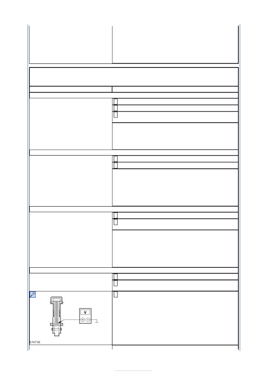
Measure the voltage between the EATC module,
connector C2H101-B, pin 14, circuit SBP27B
(BU/RD), wiring harness side and ground.
3