Ford Galaxy / Ford S-MAX. Manual - part 805
side door module.
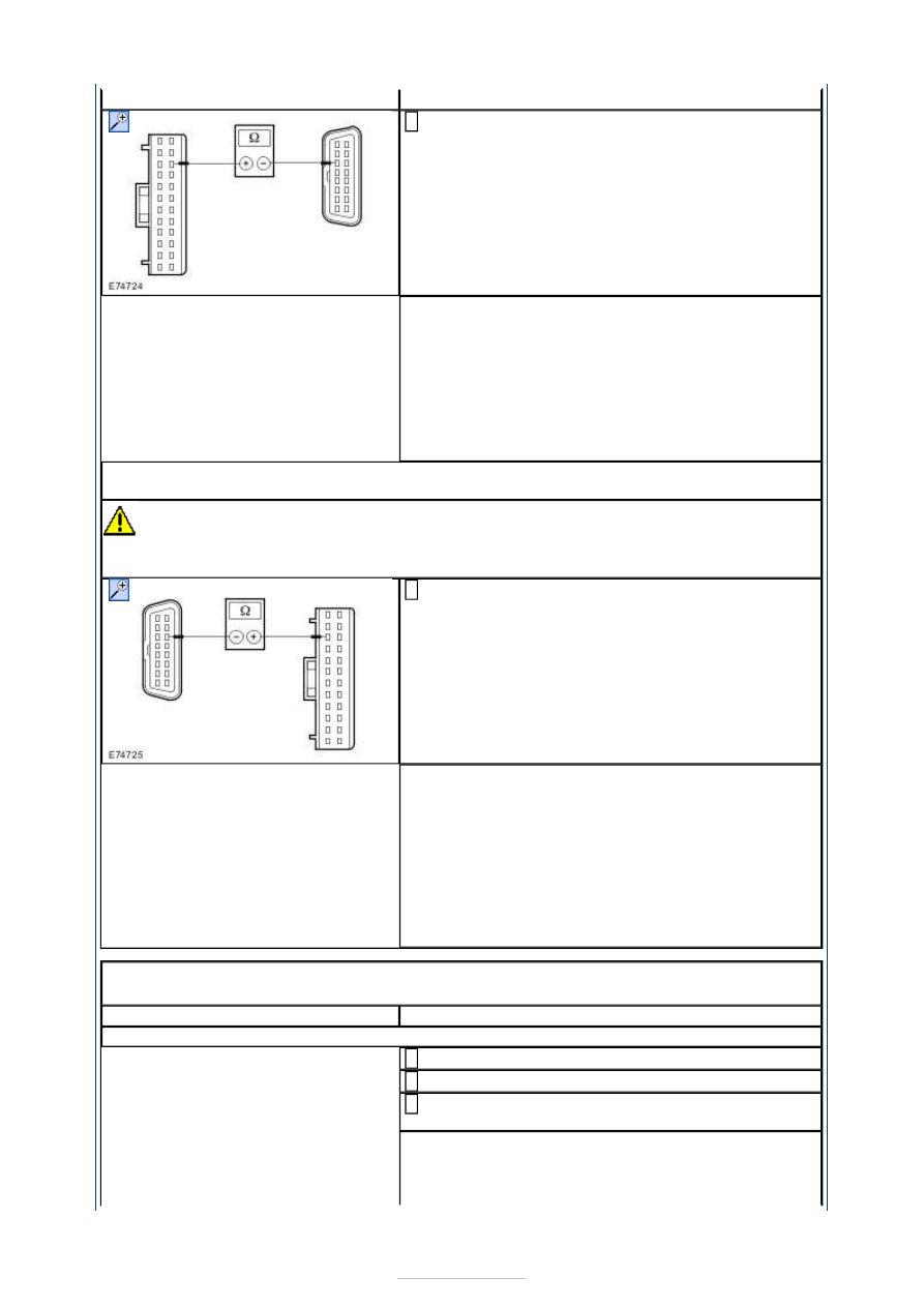
Measure the resistance between the driver's side
door module, connector C5PL01-B, pin 15, circuit
VDB07L (VT/OG), wiring harness side and the DLC,
connector C3DB04, pin 11, circuit VDB07D
(VT/OG), wiring harness side.
2
Is a resistance of less than 2 Ohms registered?
Yes
GO to A8
.
No
LOCATE and RECTIFY the break in the circuit
between the driver's side door module and soldered
connection SP286 (RHD vehicles: soldered
connection SP284) with the aid of the Wiring
Diagrams. CHECK the operation of the system.
A8: CHECK THE CIRCUIT BETWEEN THE DRIVER'S SIDE DOOR MODULE AND THE DLC
FOR OPEN CIRCUIT
CAUTION: The following measurement must only be performed using the Ford
approved diagnostic tool digital multimeter. Failure to observe this instruction can lead to
damage.
Measure the resistance between the driver's side
door module, connector C5PL01-B, pin 3, circuit
VDB06C (GY/OG), wiring harness side and the DLC,
connector C3DB04, pin 3, circuit VDB06X (GY/OG),
wiring harness side.
1
Is a resistance of less than 2 Ohms registered?
Yes
CHECK and if necessary RENEW the driver's side
door module. CHECK the operation of the system.
No
LOCATE and RECTIFY the break in the circuit
between the driver's side door module and soldered
connection SP293 (RHD vehicles: soldered
connection SP293) with the aid of the Wiring
Diagrams. CHECK the operation of the system.
PINPOINT TEST B : PASSENGER SIDE DOOR MODULE NOT
COMMUNICATING WITH THE FORD APPROVED DIAGNOSTIC TOOL
TEST CONDITIONS
DETAILS/RESULTS/ACTIONS
B1: CHECK COMMUNICATIONS WITH THE GENERIC ELECTRONIC MODULE (GEM)
Ignition switch in position 0.
1
Connect the diagnostic tool.
2
Select the generic electronic module (GEM) with
the Ford approved diagnostic tool.
3
Is it possible to establish communications with the
GEM?
Yes