Ford Galaxy / Ford S-MAX. Manual - part 810
Does the meter display battery voltage?
Yes
GO to I4
.
No
REPAIR the voltage supply to fuse F27 with the aid of
the Wiring Diagrams. CHECK the operation of the
system.
I4: CHECK THE VOLTAGE AT THE FUEL-FIRED BOOSTER HEATER / PROGRAMMABLE
FUEL-FIRED BOOSTER HEATER
Disconnect Connector C1HF01-C from the fuel-fired
booster heater / programmable fuel-fired booster
heater.
1
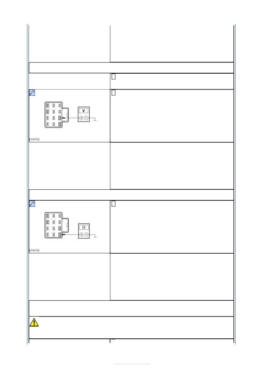
Measure the voltage between the fuel-fired booster
heater / programmable fuel-fired booster heater,
connector C1HF01-C, pin 3, circuit SBB27A (BU/RD),
wiring harness side and ground.
2
Does the meter display battery voltage?
Yes
GO to I5
.
No
LOCATE and RECTIFY the break in circuit SBB27A
(BU/RD) between the fuel-fired booster heater /
programmable fuel-fired booster heater and the EJB
with the aid of the Wiring Diagrams. CHECK the
operation of the system.
I5: CHECK THE GROUND CONNECTION OF THE FUEL-FIRED BOOSTER HEATER /
PROGRAMMABLE FUEL-FIRED BOOSTER HEATER
Measure the resistance between the fuel-fired
booster heater / programmable fuel-fired booster
heater, connector C1HF01-C, pin 4, circuit GD132L
(BK/VT), wiring harness side and ground.
1
Is a resistance of less than 2 Ohms registered?
Yes
GO to I6
.
No
LOCATE and RECTIFY the open circuit between the
fuel-fired booster heater / programmable fuel-fired
booster heater and soldered connection SP380 with
the aid of the Wiring Diagrams. CHECK the operation
of the system.
I6: CHECK FOR OPEN CIRCUIT BETWEEN THE FUEL-FIRED BOOSTER HEATER /
PROGRAMMABLE FUEL-FIRED BOOSTER HEATER AND THE DATA LINK CONNECTOR
(DLC)
CAUTION: The following measurement must only be performed using the Ford
approved diagnostic tool digital multimeter. Failure to observe this instruction can lead to
damage.