Ford Galaxy / Ford S-MAX. Manual - part 770
 

  Index      Ford     Ford Galaxy / Ford S-MAX - service repair manual 2006 year


Search            


Content   ..  768  769  770  771   ..


Ford Galaxy / Ford S-MAX. Manual - part 770


Yes 

GO to C10

.  

No 

- LHD: LOCATE and RECTIFY the break in the 
voltage supply of fuse FA1 (25 A) (RJB) with the 
aid of the Wiring Diagrams. CHECK system 
operates correctly 
- RHD: LOCATE and RECTIFY the break in the 
voltage supply of fuse FA2 (25 A) (RJB) with the 
aid of the Wiring Diagrams. CHECK system 
operates correctly 

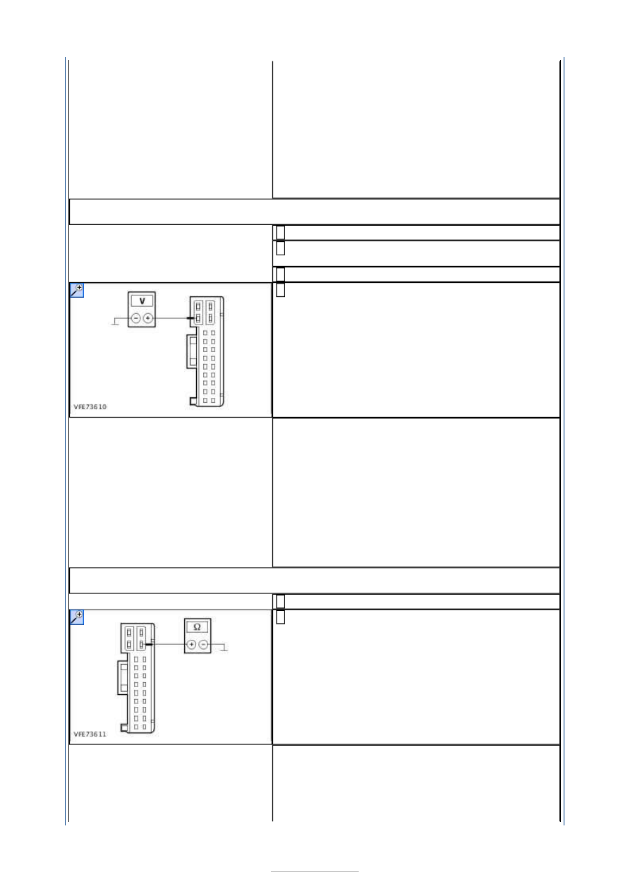
C10: CHECK THE VOLTAGE SUPPLY OF THE LEFT-HAND DOOR CONTROL MODULE FOR 
OPEN CIRCUIT

Ignition switch in position 0. 

Disconnect Door control module, left-hand side 
from connector C5PL01A. 

Ignition switch in position II. 

Measure the voltage between the door control 
module, left-hand side, connector C5PL01A, pin 2, 

circuit SBR01A (RD), wiring harness side and 
ground. 

Does the meter display battery voltage? 
Yes 

GO to C11

.  

No 

- LHD: LOCATE and RECTIFY the break in the 
circuit between the door control module and fuse 
FA1 (25 A) (RJB) with the aid of the Wiring 
Diagrams. CHECK system operates correctly 
- RHD: LOCATE and RECTIFY the break in the 
circuit between the door control module and fuse 
FA2 (25 A) (RJB) with the aid of the Wiring 
Diagrams. CHECK system operates correctly 

C11: CHECK THE GROUND CONNECTION OF THE LEFT-HAND DOOR CONTROL MODULE 
FOR OPEN CIRCUIT

Ignition switch in position 0. 

Measure the resistance between the left-hand door 
control module, connector C5PL01A, pin 13, circuit 

GD134H (BK/VT), wiring harness side and ground. 

Is a resistance of less than 2 Ohms registered? 
Yes 

GO to C12

.  

No 

LOCATE and RECTIFY the break in the circuit 
between the door control module and soldered 


connection SP386 with the aid of the Wiring 
Diagrams. CHECK system operates correctly 

C12: CHECK THE VOLTAGE SUPPLY TO THE INTEGRATED TURN SIGNAL LAMP IN THE 
LEFT-HAND EXTERIOR MIRROR FOR OPEN CIRCUIT

Connect Left-hand door control module to 
connector C5PL01A. 

Disconnect Left-hand integrated turn signal lamp 
from connector C5PM26A. 

Ignition switch in position II. 

SWITCH ON the left-hand turn signal. 

Measure the voltage between the integrated turn 
signal lamp, left-hand exterior mirror, connector 

C5PM26A, pin 7, circuit CLS22A (GN/BN), wiring 
harness side and ground. 

Is fluctuating battery voltage measured? 
Yes 

GO to C13

.  

No 

GO to C15

.  

C13: CHECK THE GROUND SUPPLY TO THE INTEGRATED TURN SIGNAL LAMP IN THE 
LEFT-HAND EXTERIOR MIRROR FOR OPEN CIRCUIT

Ignition switch in position 0. 

Measure the resistance between the integrated 
turn signal lamp, left-hand exterior mirror, 

connector C5PM26A, pin 6, circuit RPM05A 
(VT/GN), wiring harness side and ground. 

Is a resistance of less than 2 Ohms registered? 
Yes 

RENEW the integrated turn signal lamp in the 
exterior mirror CHECK system operates correctly 

No 

GO to C14

.  

C14: CHECK THE GROUND CONNECTION BETWEEN THE DOOR CONTROL MODULE AND 
THE INTEGRATED TURN SIGNAL LAMP IN THE LEFT-HAND EXTERIOR MIRROR FOR 
OPEN CIRCUIT

Disconnect Door control module, left-hand side 
from connector C5PL01B. 

Measure the resistance between the integrated 
turn signal lamp, left-hand exterior mirror, 

connector C5PM26A, pin 6, circuit RPM05A 
(VT/GN), wiring harness side and the door control 
module, left-hand side, connector C5PL01B, pin 23, 
circuit RPM05A (VT/GN), wiring harness side. 


Is a resistance of less than 2 Ohms registered? 
Yes 

RENEW the door control module. CHECK system 
operates correctly 

No 

LOCATE and RECTIFY the break in the circuit 
between the integrated turn signal lamp in the 
exterior mirror and the door control module using 
the Wiring Diagrams. CHECK system operates 
correctly 

C15: CHECK THE VOLTAGE SUPPLY TO THE INTEGRATED TURN SIGNAL LAMP IN THE 
LEFT-HAND EXTERIOR MIRROR FOR OPEN CIRCUIT

Ignition switch in position 0. 

Disconnect Left-hand door control module from 
connector C5PL01B. 

Measure the resistance between the left-hand door 
control module, connector C5PL01B, pin 11, circuit 

CLS22A (GN/BN), wiring harness side and the 
integrated turn signal lamp, left-hand exterior 
mirror, connector C5PM26A, pin 7, circuit CLS22A 
(GN/BN), wiring harness side. 

Is a resistance of less than 2 ohms registered? 
Yes 

CHECK and if necessary RENEW the door control 
module. CHECK system operates correctly If the 
concern persists:  
REFER to: 

Communications Network

 (418-00 

Module Communications Network, Diagnosis and 
Testing). 

No 

LOCATE and RECTIFY the break in the circuit 
between the door control module and the 
integrated turn signal lamp in the exterior mirror 
using the Wiring Diagrams. CHECK system operates 
correctly 

C16: CHECK THE GROUND CONNECTION TO THE RIGHT-HAND HEADLAMP FOR OPEN 
CIRCUIT

Ignition switch in position 0. 

Measure the resistance between the right-hand 
headlamp, connector C1LF09, pin 7, circuit 

GD132M (BK/VT), wiring harness side and ground. 

Measure the resistance between the right-hand 
headlamp, connector C1LF09, pin 9, circuit 

GD132X (BK/VT), wiring harness side and ground. 


Is a resistance of less than 2 Ohm measured in both 
cases? 
Yes 

GO to C17

.  

No 

LOCATE and RECTIFY the break in the circuit 
between the headlamp and soldered connection 
SP380 using the wiring diagrams. CHECK system 
operates correctly 

C17: CHECK THE VOLTAGE SUPPLY TO THE FRONT RIGHT-HAND TURN SIGNAL LAMP 
FOR OPEN CIRCUIT

Ignition switch in position II. 

SWITCH ON the right-hand turn signal. 

Measure the voltage between the right-hand 
headlamp, connector C1LF09, pin 8, circuit CLS25A 

(YE/VT), wiring harness side and ground. 

Is fluctuating battery voltage measured? 
Yes 

CHECK and if necessary RENEW the headlamp. 
CHECK system operates correctly 

No 

GO to C18

.  

C18: CHECK THE VOLTAGE SUPPLY TO THE FRONT RIGHT-HAND TURN SIGNAL LAMP 
FOR OPEN CIRCUIT

Ignition switch in position 0. 

Disconnect Smart Junction Box from connector 
C1BP02A. 

Measure the resistance between the Smart 
Junction Box, connector C1BP02A, pin 1, circuit 

CLS25A (YE/VT), wiring harness side and the right-
hand headlamp, connector C1LF09, pin 8, circuit 
CLS25A (YE/VT), wiring harness side. 

Is a resistance of less than 2 Ohms registered? 
Yes 

INSTALL A NEW Smart Junction Box. CHECK 
system operates correctly 

No 

LOCATE and RECTIFY the break in the circuit 
between the headlamp and the Smart Junction Box 
with the aid of the Wiring Diagrams. CHECK system 
operates correctly 

C19: CHECK THE GROUND CONNECTION TO THE RIGHT-HAND REAR LAMP ASSEMBLY 
FOR OPEN CIRCUIT

Ignition switch in position 0. 

Disconnect Right-hand rear lamp assembly from 
connector C4LS19A. 

Measure the resistance between the right-hand 
rear lamp assembly, connector C4LS19A, pin 3, 

circuit GD152A (BK/BU), wiring harness side and 
ground. 

Is a resistance of less than 2 Ohms registered? 
Yes 


Content   ..  768  769  770  771   ..