Ford Galaxy / Ford S-MAX. Manual - part 771
GO to C20
.
No
LOCATE and RECTIFY the break in the circuit
between the rear lamp assembly and soldered
connection SP600 with the aid of the Wiring
Diagrams. CHECK system operates correctly
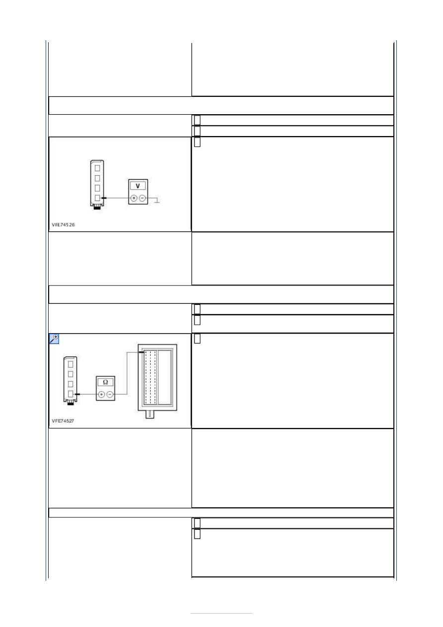
C20: CHECK VOLTAGE SUPPLY TO RIGHT-HAND REAR LAMP ASSEMBLY FOR OPEN
CIRCUIT
Ignition switch in position II.
1
SWITCH ON the right-hand turn signal.
2
Measure the voltage between the right-hand rear
lamp assembly, connector C4LS19A, pin 4, circuit
CLS27A (GN/OG), wiring harness side and ground.
3
Is fluctuating battery voltage measured?
Yes
CHECK and if necessary RENEW the right-hand rear
lamp assembly. CHECK system operates correctly
No
GO to C21
.
C21: CHECK VOLTAGE SUPPLY TO RIGHT-HAND REAR LAMP ASSEMBLY FOR OPEN
CIRCUIT
Ignition switch in position 0.
1
Disconnect Smart Junction Box from connector
C1BP02B.
2
Measure the resistance between the Smart
Junction Box, connector C1BP02B, pin 18, circuit
CLS27A (GN/OG), wiring harness side and the rear
right lamp assembly, connector C4LS19A, pin 4,
circuit CLS27A (GN/OG), wiring harness side.
3
Is a resistance of less than 2 Ohms registered?
Yes
INSTALL A NEW Smart Junction Box. CHECK
system operates correctly
No
LOCATE and RECTIFY the break in the circuit
between the rear lamp assembly and the Smart
Junction Box with the aid of the Wiring Diagrams.
CHECK system operates correctly
C22: CHECK FUSE FA2/FA1 (25 A) (RJB)
Ignition switch in position 0.
1
Disconnect Fuse.
LHD: FA2 (25 A) (RJB)
RHD: FA1 (25 A) (RJB)
2