Ford Galaxy / Ford S-MAX. Manual - part 769
wiring diagrams. CHECK system operates correctly
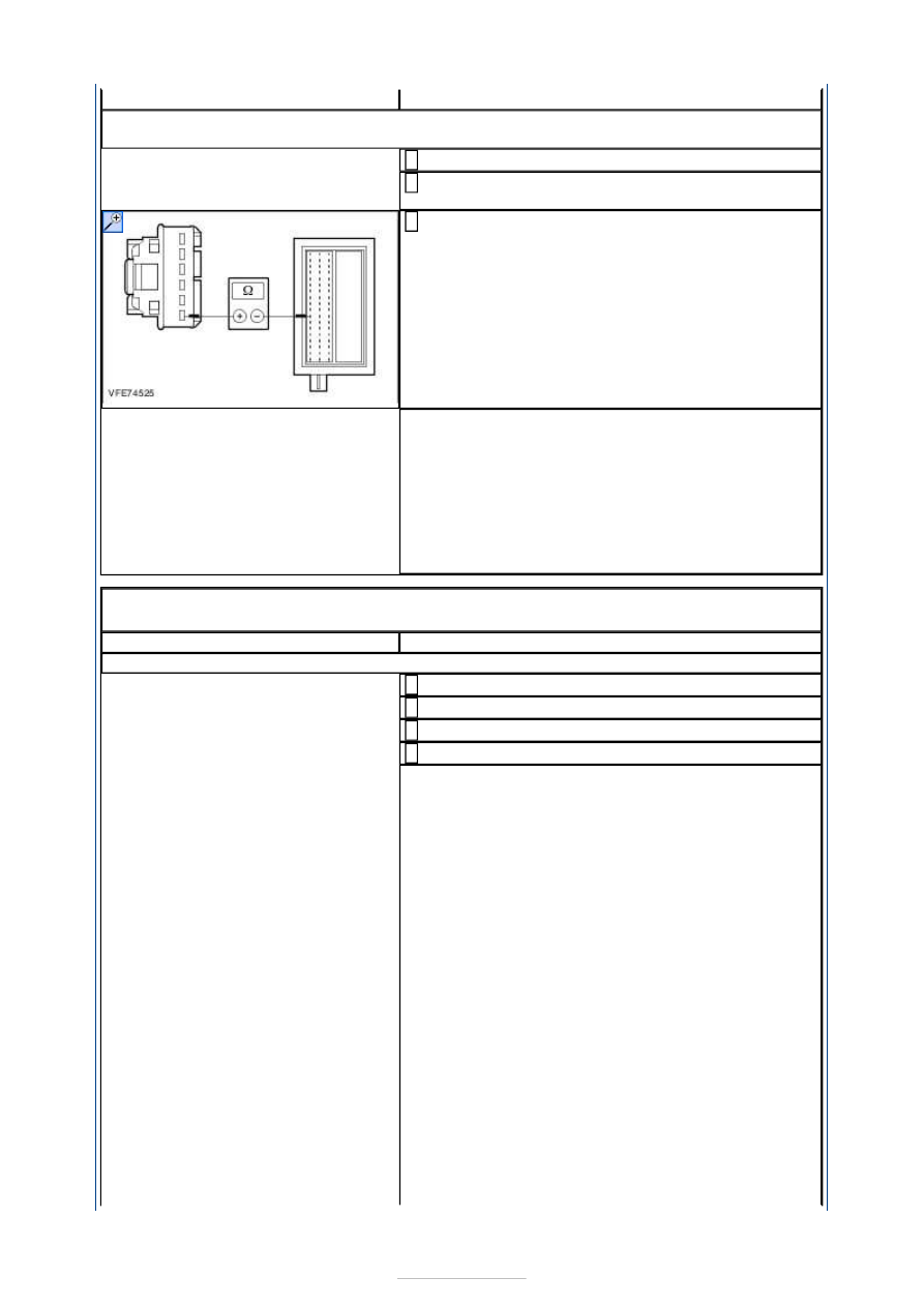
B3: CHECK THE CIRCUIT BETWEEN THE HAZARD WARNING LIGHTS SWITCH AND THE
SMART JUNCTION BOX FOR OPEN CIRCUIT
Ignition switch in position 0.
1
Disconnect Smart Junction Box from connector
C1BP02C.
2
Measure the resistance between the hazard
warning lights switch, connector C2LS32, pin 6,
circuit CLS32A (BN/YE), wiring harness side and
the Smart Junction Box, connector C1BP02C, pin 8,
circuit CLS32A (BN/YE), wiring harness side.
3
Is a resistance of less than 2 Ohms registered?
Yes
INSTALL A NEW Smart Junction Box. CHECK
system operates correctly
No
LOCATE and RECTIFY the break in the circuit
between the hazard warning lights switch and the
Smart Junction Box with the aid of the Wiring
Diagrams. CHECK system operates correctly
PINPOINT TEST C : SINGLE OR MULTIPLE TURN SIGNAL LAMPS
INOPERATIVE
TEST CONDITIONS
DETAILS/RESULTS/ACTIONS
C1: DETERMINE THE CONDITION UNDER WHICH THE FAULT OCCURS
Ignition switch in position II.
1
CHECK the turn signal lamps.
2
SWITCH ON the left-hand turn signal.
3
SWITCH ON the right-hand turn signal.
4
Is one or more turn signal lamp on the left-hand side
inoperative?
Yes
- All turn signal lamps on left-hand side
inoperative: CHECK and if necessary RENEW the
steering wheel/steering column switch. CHECK
system operates correctly If the concern persists:
REFER to:
Communications Network
(418-00
Module Communications Network, Diagnosis and
Testing).
- Left-hand front turn signal lamp is inoperative:
GO to C2
.
- Left-hand rear turn signal lamp is inoperative:
GO
to C5
.
- Integrated turn signal lamp in the left-hand
exterior mirror is inoperative:
GO to C8
.
No
- All turn signal lamps on right-hand side
inoperative: CHECK and if necessary RENEW the
steering wheel/steering column switch. CHECK
system operates correctly If the concern persists:
REFER to:
Communications Network
(418-00
Module Communications Network, Diagnosis and
Testing).