Ford Galaxy / Ford S-MAX. Manual - part 768
 

  Index      Ford     Ford Galaxy / Ford S-MAX - service repair manual 2006 year


Search            


Content   ..  766  767  768  769   ..


Ford Galaxy / Ford S-MAX. Manual - part 768


A8: CHECK THE GROUND CONNECTION OF THE STEERING WHEEL/STEERING COLUMN 
MODULE FOR OPEN CIRCUIT

Ignition switch in position 0. 

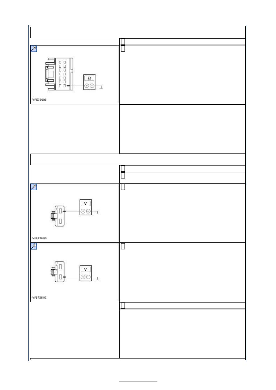
Measure the resistance between the steering 
wheel/steering column module, connector C2LS41, 

pin 14, circuit GD138AY (BK/WH), wiring harness 
side and ground. 

Is a resistance of less than 2 Ohms registered? 
Yes 

GO to A9

.  

No 

LOCATE and RECTIFY the break in the circuits 
between the steering wheel/steering column 
module and soldered connection SP518 with the aid 
of the Wiring Diagrams. CHECK system operates 
correctly 

A9: CHECK THE VOLTAGE SUPPLY TO THE SMART JUNCTION BOX (SJB) FOR OPEN 
CIRCUIT 

Ignition switch in position 0. 

Disconnect Smart Junction Box from connector 
C1BP02G. 

Measure the voltage between the Smart Junction 
Box, connector C1BP02G, pin 1, circuit SBB17A 

(RD), wiring harness side and ground. 

Measure the voltage between the Smart Junction 
Box, connector C1BP02G, pin 2, circuit SBB18A 

(YE), wiring harness side and ground. 

Ignition switch in position II. 

Is battery voltage measured in both cases? 
Yes 

GO to A10

.  

No 

LOCATE and RECTIFY the break in the relevant 
circuits between fuse F17 (60 A) (EJB) or F18 (60 
A) (EJB) and the Smart Junction Box with the aid of 
the Wiring Diagrams. CHECK system operates 
correctly 


A10: CHECK THE GROUND CONNECTION OF THE SMART JUNCTION BOX FOR OPEN 
CIRCUIT 

Ignition switch in position 0. 

Measure the resistance between the Smart 
Junction Box, connector C1BP02A, pin 54, circuit 

GD123F (BK/GY), wiring harness side and ground. 

Is a resistance of less than 2 Ohms registered? 
Yes 

GO to A11

.  

No 

LOCATE and RECTIFY the break in the circuits 
between the Smart Junction Box and ground 
connection G1D132B with the aid of the Wiring 
Diagrams. CHECK system operates correctly 

A11: CHECK THE GROUND CONNECTION OF THE SMART JUNCTION BOX FOR OPEN 
CIRCUIT 

Ignition switch in position 0. 

Measure the resistance between the Smart 
Junction Box, connector C1BP02A, pin 65: 

LHD: circuit GD140J (BK/GN), wiring harness 
side and ground. 

RHD: circuit GD134U (BK/VT), wiring harness 
side and ground. 

Is a resistance of less than 2 Ohms registered? 
Yes 

GO to A12

.  

No 

- LHD: LOCATE and RECTIFY the break in the 
circuits between the Smart Junction Box and 
ground connection G3D138 with the aid of the 
Wiring Diagrams. CHECK system operates correctly 
- RHD: LOCATE and RECTIFY the break in the 
circuits between the Smart Junction Box and 
ground connection G3D133 with the aid of the 
Wiring Diagrams. CHECK system operates correctly 

A12: CHECK THE LIN DATA BUS CONNECTION BETWEEN THE STEERING 
WHEEL/STEERING COLUMN MODULE AND THE SMART JUNCTION BOX FOR SHORT 
CIRCUIT TO BATTERY VOLTAGE

Ignition switch in position II. 

Measure the voltage between the steering 
wheel/steering column module, connector C2LS41, 

pin 2, circuit VMC34A (WH), wiring harness side 
and ground. 


Does the meter display battery voltage? 
Yes 

GO to A13

.  

No 

LOCATE and RECTIFY the short to battery voltage 
in the circuits between the steering wheel/steering 
column module and the Smart Junction Box with 
the aid of the Wiring Diagrams. CHECK system 
operates correctly 

A13: CHECK THE LIN DATA BUS CONNECTION BETWEEN THE LIGHTS CONTROL 
MODULE AND THE SMART JUNCTION BOX FOR SHORT TO GROUND

Ignition switch in position 0. 

Measure the resistance between the steering 
wheel/steering column module, connector C2LS41, 

pin 2, circuit VMC34A (WH), wiring harness side 
and ground. 

Is a resistance of more than 10,000 Ohm measured? 
Yes 

GO to A14

.  

No 

LOCATE and RECTIFY the short to ground in the 
circuits between the steering wheel/steering 
column module and the Smart Junction Box with 
the aid of the Wiring Diagrams. CHECK system 
operates correctly 

A14: CHECK THE LIN DATA BUS CONNECTION BETWEEN THE STEERING 
WHEEL/STEERING COLUMN MODULE AND THE SMART JUNCTION BOX (SJB) FOR 
OPEN CIRCUIT 

Measure the resistance between the steering 
wheel/steering column module, connector C2LS41, 

pin 2, circuit VMC34A (WH), wiring harness side 
and the Smart Junction Box, connector C1BP02C, 
pin 51, circuit VMC34A (WH), wiring harness side. 

Is a resistance of less than 2 Ohms registered? 
Yes 

RENEW the steering wheel/steering column module 


CHECK system operates correctly If the concern 
persists:  
REFER to: 

Communications Network

 (418-00 

Module Communications Network, Diagnosis and 
Testing). 

No 

LOCATE and RECTIFY the break in the circuits 
between the steering wheel/steering column 
module and the Smart Junction Box with the aid of 
the Wiring Diagrams. CHECK system operates 
correctly 

PINPOINT TEST B : HAZARD WARNING LIGHTS INOPERATIVE, TURN 
SIGNAL FUNCTION OK 

TEST CONDITIONS

DETAILS/RESULTS/ACTIONS

B1: RULE OUT THE HIGH BEAM HEADLAMP SWITCH HAZARD WARNING LIGHT 
SYSTEM AS THE CAUSE OF THE FAULT

Ignition switch in position 0. 

Disconnect Hazard warning lights switch from 
connector C2LS32. 

Connect a fused jumper lead (5 A) to the hazard 
warning lights switch, connector C2LS32, between 

pin 6, circuit CLS32A (BN/YE) and pin 4, circuit 
GD133CF (BK), wiring harness side. 

Ignition switch in position II. 

CHECK the turn signal lamps. 

Do the hazard indicators operate? 
Yes 

INSTALL A NEW hazard warning lights switch. 
CHECK system operates correctly 

No 

GO to B2

.  

B2: CHECK THE GROUND CONNECTION OF THE HAZARD WARNING LIGHTS SWITCH 
FOR OPEN CIRCUIT

Measure the resistance between the hazard 
warning lights switch, connector C2LS32, pin 4, 

circuit GD133CF (BK), wiring harness side and 
ground. 

Is a resistance of less than 2 Ohms registered? 
Yes 

GO to B3

.  

No 

LOCATE and RECTIFY the break in the circuit 
between the hazard warning lights switch and 
ground connection G3D134 with the aid of the 


Content   ..  766  767  768  769   ..