Ford Galaxy / Ford S-MAX. Manual - part 738
 

  Index      Ford     Ford Galaxy / Ford S-MAX - service repair manual 2006 year


Search            


Content   ..  736  737  738  739   ..


Ford Galaxy / Ford S-MAX. Manual - part 738


Pinpoint Tests 

CAUTION: Remove the DVD ROM before removing the navigation system DVD unit 

for circuit testing. Failure to follow this instruction may result in damage to the DVD ROM. 
NOTE: Use a digital multimeter for all electrical measurements. 

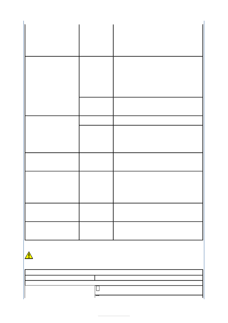
Circuit(s). 
Navigation 

system display 
module. 

Navigation 

system DVD 
unit. 

*
*

*

GO to Pinpoint Test 

B. 


*

The audio unit is 
inoperative/does not 
operate correctly

Instrument 

cluster. 

Audio unit. 
Navigation 

system display 
module. 

Navigation 

system DVD 
unit. 

*

*
*

*

CHECK all communication between the 

instrument cluster, audio unit, navigation 
system display module and navigation 
system DVD unit. REFER to the WDS.  

*

Compact disc 

(CD) changer. 

*

REFER to: Information and Entertainment 

System (415-00 Information and 
Entertainment System - General Information, 
Diagnosis and Testing). 

*

The display is blank

Instrument 

cluster. 

*

REFER to WDS.  

*

Navigation 

system display 
module. 

Navigation 

system DVD 
unit. 

*

*

GO to Pinpoint Test 

B. 


*

Poor quality/distorted sound 
from one or more speakers 
(not all speakers)

Speaker(s). 
Circuit. 
Audio unit. 

*
*
*

REFER to: Information and Entertainment 

System (415-00 Information and 
Entertainment System - General Information, 
Diagnosis and Testing). 

*

No sound from all speakers

Audio unit. 

*

INSTALL a new audio unit.  

REFER to: Navigation System Display Module 
- Vehicles With: DVD Navigation System with 
Touchscreen (415-01 Information and 
Entertainment System, Removal and 
Installation). 
TEST the system for normal operation. 

*

No sound from one or more 
of the speakers (not all 
speakers)

Speaker(s). 
Circuit. 
Audio unit. 

*
*
*

REFER to: Information and Entertainment 

System (415-00 Information and 
Entertainment System - General Information, 
Diagnosis and Testing). 

*

The auxiliary audio control is 
inoperative/does not 
operate correctly.

Circuit. 
Audio control 

switch. 

Audio unit. 

*
*

*

REFER to: Information and Entertainment 

System (415-00 Information and 
Entertainment System - General Information, 
Diagnosis and Testing). 

*

PINPOINT TEST A : NAVIGATION SYSTEM WILL NOT SWITCH ON 

TEST CONDITIONS

DETAILS/RESULTS/ACTIONS

A1: CHECK THE NAVIGATION SYSTEM DISPLAY MODULE FOR VOLTAGE

Disconnect Navigation System Display Module 
C2ME03-F. 

Ignition switch in position I. 

Measure the voltage between the navigation system 
display module C2ME03-F pin 1, circuit SBP06J 

(BN/RD), harness side and ground; and between the 
navigation system display module C2ME03-F pin 2, 
circuit CDC33D (VT/GN), harness side and ground. 

Are the voltages greater than 10 volts? 
Yes 

GO to A2

.  

No 

REPAIR circuit SBP06J (BN/RD) or circuit CDC33D 
(VT/GN). TEST the system for normal operation. 

A2: CHECK THE NAVIGATION SYSTEM DISPLAY MODULE GROUND CIRCUITS FOR 
OPEN CIRCUIT

Ignition switch in position 0. 

Measure the resistance between the navigation 
system display module C2ME03-F pin 11, circuit 

GD138BF (BK/WH), harness side and ground; and 
between the navigation system display module 
C2ME03-F pin 12, circuit GD138BG (BK/WH), harness 
side and ground. 

Are the resistances less than 1 ohm? 
Yes 

INSTALL a new navigation system display module.  
REFER to: Navigation System Display Module - 
Vehicles With: DVD Navigation System with 
Touchscreen (415-01 Information and Entertainment 
System, Removal and Installation). 
TEST the system for normal operation.  

No 

REPAIR circuit GD138BF (BK/WH) or GD138BG 
(BK/WH). TEST the system for normal operation. 

PINPOINT TEST B : NAVIGATION SYSTEM DOES NOT OPERATE CORRECTLY 

TEST CONDITIONS

DETAILS/RESULTS/ACTIONS

B1: CHECK THE NAVIGATION SYSTEM DVD UNIT FOR VOLTAGE

Disconnect Navigation System DVD Unit C2ME04. 

Measure the voltage between the navigation system 
DVD unit C2ME04 pin 1, circuit SBP06F (BN/RD), 

harness side and ground. 

Is the voltage greater than 10 volts? 
Yes 

GO to B2

.  


No 

REPAIR the circuit SBP06F (BN/RD). TEST the system 
for normal operation. 

B2: CHECK THE NAVIGATION SYSTEM DVD UNIT GROUND CIRCUIT FOR OPEN 
CIRCUIT

Measure the resistance between the navigation 
system DVD unit C2ME04 pin 13, circuit GD138BH 

(BK/WH), harness side and ground. 

Is the resistance less than 1 ohm? 
Yes 

GO to B3

.  

No 

REPAIR the circuit GD138BH (BK/WH). TEST the 
system for normal operation. 

B3: CHECK CIRCUIT CMN13A (YE/OG) FOR OPEN CIRCUIT

Disconnect Navigation System Display Module 
C2ME03-F. 

Measure the resistance between the navigation 
system display module C2ME03-F pin 4, circuit 

CMN13A (YE/OG), harness side and the navigation 
system DVD unit C2ME04 pin 2, circuit CMN13A 
(YE/OG), harness side. 

Is the resistance less than 5 ohms? 
Yes 

GO to B4

.  

No 

REPAIR the circuit. TEST the system for normal 
operation. 

B4: CHECK CIRCUIT DMN08A (NO) FOR OPEN CIRCUIT

Measure the resistance between the navigation 
system display module C2ME03-F pin 18, circuit 

DMN08A (NO), harness side and the navigation 
system DVD unit C2ME04 pin 23, circuit DMN08A 
(NO), harness side. 

Is the resistance less than 1 ohm? 
Yes 

GO to B5

.  

No 

REPAIR the circuit. TEST the system for normal 
operation. 

B5: CHECK CIRCUIT VMN08A (VT/GY) FOR OPEN CIRCUIT

Measure the resistance between the navigation 


system display module C2ME03-F pin 8, circuit 
VMN08A (VT/GY), harness side and the navigation 
system DVD unit C2ME04 pin 10, circuit VMN08A 
(VT/GY), harness side. 

Is the resistance less than 1 ohm? 
Yes 

GO to B6

.  

No 

REPAIR the circuit. TEST the system for normal 
operation. 

B6: CHECK CIRCUIT VMN09A (VT/GY) FOR OPEN CIRCUIT

Measure the resistance between the navigation 
system display module C2ME03-F pin 19, circuit 

VMN09A (VT/GY), harness side and the navigation 
system DVD unit C2ME04 pin 22, circuit VMN09A 
(VT/GY), harness side. 

Is the resistance less than 1 ohm? 
Yes 

GO to B7

.  

No 

REPAIR the circuit. TEST the system for normal 
operation. 

B7: CHECK CIRCUIT VMN10A (BU/WH) FOR OPEN CIRCUIT

Measure the resistance between the navigation 
system display module C2ME03-F pin 20, circuit 

VMN10A (BU/WH), harness side and the navigation 
system DVD unit C2ME04 pin 9, circuit VMN10A 
(BU/WH), harness side. 

Is the resistance less than 1 ohm? 
Yes 

GO to B8

.  

No 

REPAIR the circuit. TEST the system for normal 
operation. 

B8: CHECK CIRCUIT VMN11A (GR/RD) FOR OPEN CIRCUIT

Measure the resistance between the navigation 
system display module C2ME03-F pin 10, circuit 

VMN11A (GR/RD), harness side and the navigation 
system DVD unit C2ME04 pin 21, circuit VMN11A 
(GR/RD), harness side. 


Content   ..  736  737  738  739   ..