Ford Galaxy / Ford S-MAX. Manual - part 736
Pinpoint Tests
CAUTION: If the navigation system display module is to be removed for testing or
new component installation, remove any audio media (if possible) from within the
navigation system display module and return it to the customer. Failure to follow this
instruction may result in damage to the navigation system display module.
NOTE: Use a digital multimeter for all electrical measurements.
(415-01 Information and Entertainment System, Removal
and Installation).
TEST the system for normal operation.
PINPOINT TEST A : NAVIGATION SYSTEM WILL NOT SWITCH ON
TEST CONDITIONS
DETAILS/RESULTS/ACTIONS
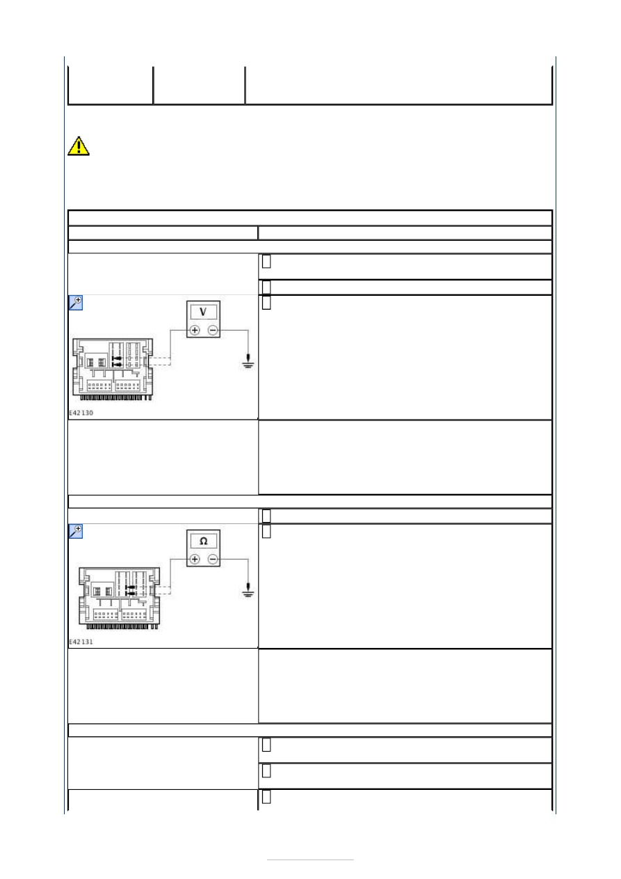
A1: CHECK FOR VOLTAGE TO NAVIGATION SYSTEM DISPLAY MODULE
Disconnect Navigation System Display Module
CME03B.
1
Ignition switch in position I.
2
Measure the voltage between the navigation system
display module C2ME03-A pin 15, circuit SBP06E
(BN/RD), harness side and ground; and between the
navigation system display module C2ME03-A pin 16,
circuit CDC33C (VT/GN), harness side and ground.
3
Are the voltages greater than 10 volts?
Yes
GO to A2
.
No
REPAIR circuit SBP06E (BN/RD) or circuit CDC33C
(VT/GN). TEST the system for normal operation.
A2: CHECK THE NAVIGATION SYSTEM DISPLAY MODULE FOR GROUND
Ignition switch in position 0.
1
Measure the resistance between the navigation
system display module C2ME03-A pin 11, circuit
GD103C (BK/BU), harness side and ground; and
between the navigation system display module
C2ME03-A pin 12, circuit GD103A (BK/BU), harness
side and ground.
2
Are the resistances less than 1 ohm?
Yes
GO to A3
.
No
REPAIR circuit GD103C (BK/BU) or circuit GD103A
(BK/BU). TEST the system for normal operation.
A3: CHECK CIRCUIT RME24A (BU/WH) TO GROUND
Connect Navigation System Display Module C2ME03-
A.
1
Disconnect Navigation System Display Module
C2ME03-B.
2
Measure the resistance between the navigation
3