Ford Galaxy / Ford S-MAX. Manual - part 735
 

  Index      Ford     Ford Galaxy / Ford S-MAX - service repair manual 2006 year


Search            


Content   ..  733  734  735  736   ..


Ford Galaxy / Ford S-MAX. Manual - part 735


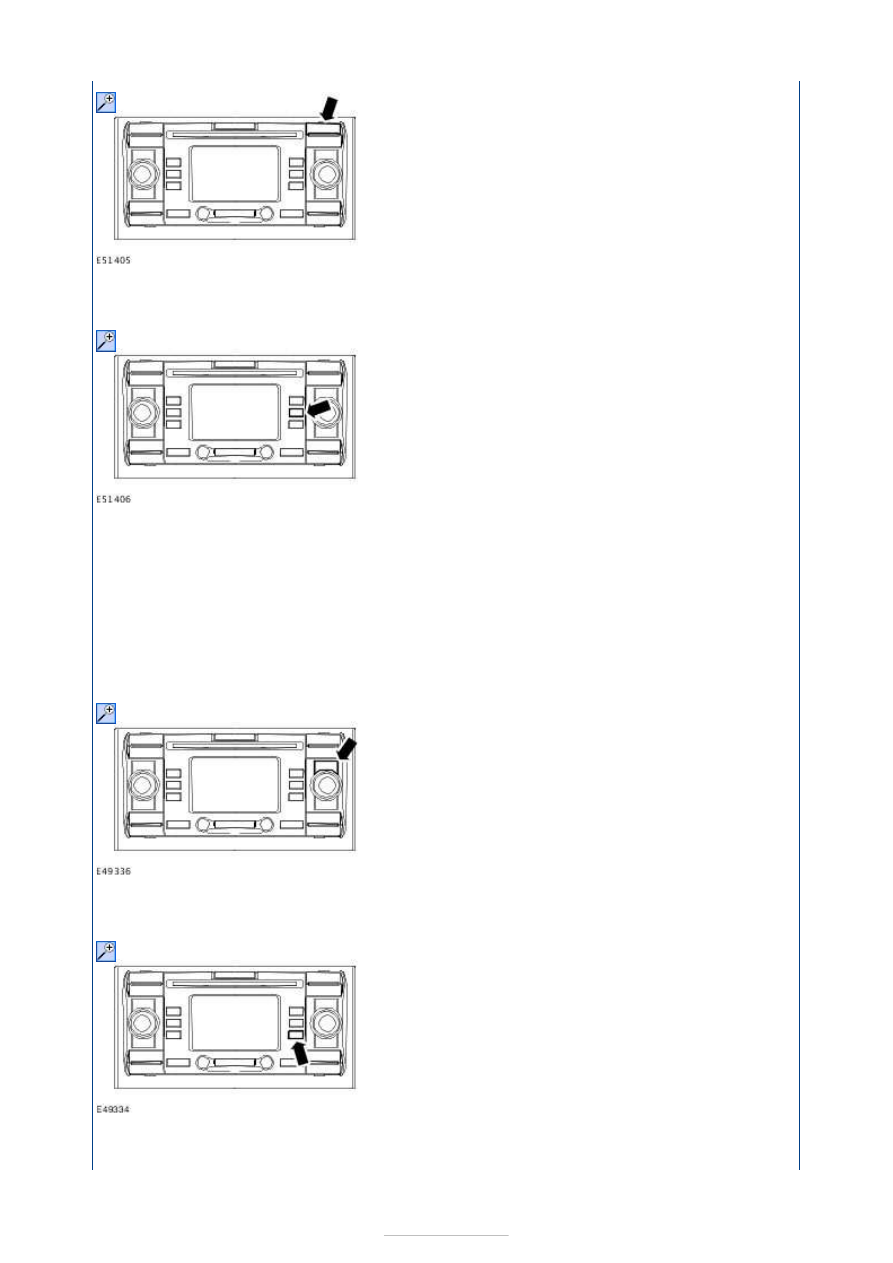
1. 1. PRESS the NAV button 

2. 2. PRESS the S5 button to enter the GPS INFO menu. 

NOTE: The minimum number of satellites received by the navigation system display 
module for correct operation is four. If the satellites received is below the minimum 
requirement, the navigation system will not operate correctly. Move the vehicle to a 
position where the required amount of satellites are received. 

3. 3. Check the amount of satellites received by the navigation system display module. 

4. 4. PRESS ESC to return to the previous menu. 

5. 5. With the navigation system display module in the navigation main menu, PRESS 


the S6 (EXTRA) button. 

NOTE: ROTATE the right-hand rotary knob to highlight the mode required and PRESS the 
right-hand rotary knob (ENTER) to select the mode. 

6. 6. SELECT SENSOR TEST and PRESS the right-hand rotary knob. CHECK that all of 

the sensors shown on the screen are operating correctly. 

NOTE: When checking the wheel speed sensor it is necessary to drive the vehicle ten 
meters forwards above 4 km/h (2.5 mph) to make the value change. 
NOTE: When checking the direction sensor select the reverse gear and drive the vehicle 
ten meters rearwards above 4 km/h (2.5 mph) to make the value change. 
NOTE: When checking the navigation system display module internal gyroscope manually 
move the vehicle from side to side to make the value change. If the value does not 
change when the vehicle is being moved, INSTALL a new navigation system display 
module.  
REFER to: 

Audio Unit - Vehicles With: Travel Pilot EX

 (415-01 Information and 

Entertainment System, Removal and Installation). 
NOTE: When checking the GPS antenna self-diagnostic function, disconnect the GPS 
antenna from the rear of the navigation system display module and TEST the system for 
normal operation.  
REFER to: 

Audio Unit - Vehicles With: Travel Pilot EX

 (415-01 Information and 

Entertainment System, Removal and Installation). 
If the navigation system display module is operating correctly, the display will show a 
GPS error. If no message is displayed with the GPS antenna disconnected, INSTALL a new 
navigation system display module.  
REFER to: 

Audio Unit - Vehicles With: Travel Pilot EX

 (415-01 Information and 

Entertainment System, Removal and Installation). 
NOTE: Connect the GPS antenna to the navigation system display module and REFER to 
the following list to diagnose the GPS antenna. 
NOTE: The following list will not apply if the fault is induced by disconnecting the GPS 
antenna. 

If the GPS antenna sensor test displays OPEN, the GPS antenna is open circuit. REFER to 
the DTC Index Chart and DTC TBD13 ACTION. Follow the instructions to diagnose the 
GPS antenna.  
If the GPS antenna sensor test displays SHORT, the GPS antenna is out of specification. 
REFER to the WDS, check the DTCs. If DTC TBD12 is retrieved, REFER to the DTC Index 
Chart to diagnose the GPS antenna.  
If the GPS antenna sensor test displays OK, the GPS antenna is OK. 


7. 7. PRESS ESC to return to the previous menu. 

8. 8. If the cause is not visually evident after the Self-Diagnostic Mode, connect the 

WDS to the data link connector (DLC). 

9.

NOTE: Do not select the NAV from the WDS menu as this is for vehicles with digital 
versatile disc (DVD) navigation system with touchscreen. 

9. Select the ACU from the WDS menu. 

10. 10. Retrieve the DTCs and refer to the DTC Index Chart. 

Diagnostic Trouble Code (DTC) Index Chart 

DTC

Description/Condition Possible Source

Action

B1342

Navigation system 

display module failure

Navigation 

system display 

module

INSTALL a new navigation system display 

module.  

REFER to: 

Audio Unit - Vehicles With: Travel 

Pilot EX

 (415-01 Information and 

Entertainment System, Removal and 

Installation). 

TEST the system for normal operation.

B2408 Speaker line short circuit

Speaker(s), 

Circuit(s)

REFER to: 

Information and Entertainment 

System

 (415-00 Information and 

Entertainment System - General Information, 

Diagnosis and Testing).

B1097 Tweeter line short circuit

Speaker(s), 

Circuit(s)

REFER to: 

Information and Entertainment 

System

 (415-00 Information and 

Entertainment System - General Information, 

Diagnosis and Testing).

B1893 GPS antenna connection 

open circuit

Antenna fault 

open circuit

CHECK the navigation system antenna 

connections and antenna base ground 

connection. TEST the system for normal 

operation. IF the concern persists, INSTALL a 

new navigation system antenna cable. 

B2204 GPS antenna connection 

short circuit

Antenna fault 

short

Disconnect the navigation system antenna. 

TEST the system for normal operation. If the 

DTC is still present with the navigation 

system antenna disconnected, INSTALL a 

new navigation system display module.  

REFER to: 

Audio Unit - Vehicles With: Travel 

Pilot EX

 (415-01 Information and 

Entertainment System, Removal and 

Installation). 

IF the DTC B1893 is shown, REFER to DTC 

B1893 in this section. 

B2206

Gyroscope error

Invalid values 

from gyroscope 

for 30 seconds

INSTALL a new navigation system display 

module.  

REFER to: 

Audio Unit - Vehicles With: Travel 


1. 1. If the cause is not evident, verify the symptom and refer to the Symptom Chart. 

Symptom Chart 

Pilot EX

 (415-01 Information and 

Entertainment System, Removal and 

Installation). 

TEST the system for normal operation.

B2477

Module configuration 

failure

Navigation 

system display 

module not 

configured

REFER to the WDS.

U1900 Controller area network 

(CAN) BUS failure

CAN

REFER to: Communications Network (418-00, 

Diagnosis and Testing).

B2406 Internal audio CD player 

failure

Navigation 

system display 

module

INSTALL a new navigation system display 

module.  

REFER to: 

Audio Unit - Vehicles With: Travel 

Pilot EX

 (415-01 Information and 

Entertainment System, Removal and 

Installation). 

TEST the system for normal operation.

B1035

CD ROM read test

CD ROM

INSPECT the CD ROM for damage. INSTALL a 

new CD ROM. TEST the system for normal 

operation.

B2410 FM receiving signal error

Antenna cable

REFER to: 

Information and Entertainment 

System

 (415-00 Information and 

Entertainment System - General Information, 

Diagnosis and Testing).

B1317

Battery voltage low

Battery voltage 

below 9 volts

REFER to: 

Charging System

 (414-00 

Charging System - General Information, 

Diagnosis and Testing).

B1318

Battery voltage high

Battery voltage 

above 16 volts

REFER to: 

Charging System

 (414-00 

Charging System - General Information, 

Diagnosis and Testing).

Symptom

Possible Sources

Action

Navigation 
system does not 
operate but 
radio does

Incorrectly 

installed 
navigation CD 
ROM. 

*

Install the navigation CD ROM correctly. 

*

Navigation 
system will not 
switch on

Circuit(s). 
Navigation 

system display 
module. 

*
*

GO to Pinpoint Test 

A. 


*

Navigation 
system not 
operating 
correctly

Wheel speed 

sensor. 

*

REFER to: Road Test Form - Anti-Lock Brake System 

(ABS) (206-09A Anti-Lock Control, Diagnosis and 
Testing). 

*

Antenna 

signal. 

*

REFER to the Self-Diagnostic Mode. 

*

Reversing 

lamp(s). 

*

REFER to: 

Reversing Lamps

 (417-01 Exterior Lighting, 

Diagnosis and Testing). 

*

Gyroscope. 

*

With the navigation system display module in Self-

Diagnostic Mode, check the Gyro value changes when the 
vehicle is moved side to side. If the value changes with 
the movement of the vehicle, the internal gyroscope is 
operating correctly. If the value does not change, 
INSTALL a new navigation system display module.  
REFER to: 

Audio Unit - Vehicles With: Travel Pilot EX


*


Content   ..  733  734  735  736   ..