Ford Galaxy / Ford S-MAX. Manual - part 733
 

  Index      Ford     Ford Galaxy / Ford S-MAX - service repair manual 2006 year


Search            


Content   ..  731  732  733  734   ..


Ford Galaxy / Ford S-MAX. Manual - part 733


Is the resistance less than 1 ohm? 
Yes 

GO to E8

.  

No 

REPAIR the circuit(s) as necessary. TEST the system 
for normal operation. 

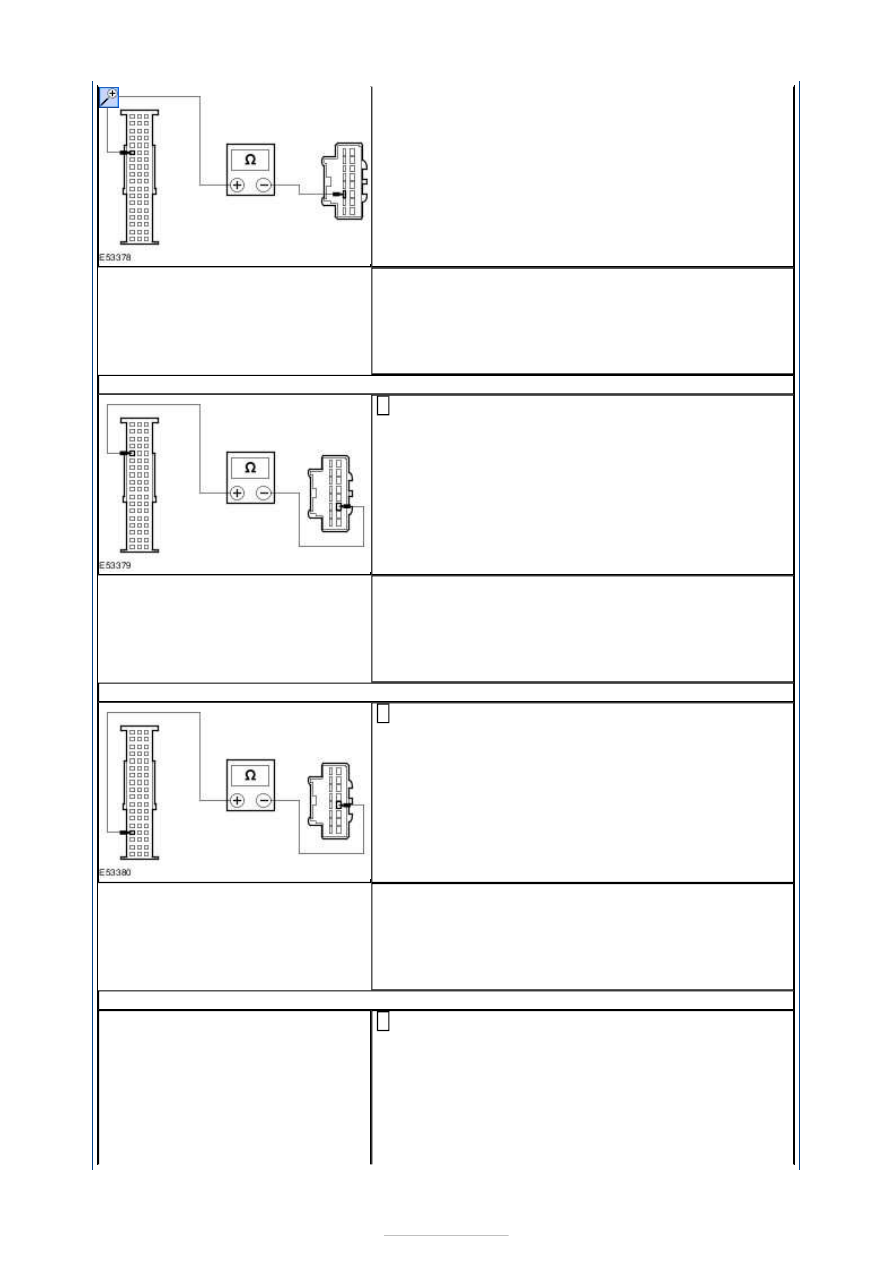
E8: CHECK CIRCUIT CMM19A (BN/YE) TO CIRCUIT CMM19B (BN/YE) FOR OPEN

Measure the resistance between the PSE module 
C2MM01-B pin 41, circuit CMM19A (BN/YE), harness 

side and the handset holder C2MM17-A pin 11, circuit 
CMM19B (BN/YE), harness side. 

Is the resistance less than 1 ohm? 
Yes 

GO to E9

.  

No 

REPAIR the circuit(s) as necessary. TEST the system 
for normal operation. 

E9: CHECK CIRCUIT VMM20A (GN/BN) TO CIRCUIT VMM20B (GN/BN) FOR OPEN

Measure the resistance between the PSE module 
C2MM01-B pin 51, circuit VMM20A (GN/BN), harness 

side and the handset holder C2MM17-A pin 12, circuit 
VMM20B (GN/BN), harness side. 

Is the resistance less than 1 ohm? 
Yes 

GO to E10

.  

No 

REPAIR the circuit(s) as necessary. TEST the system 
for normal operation. 

E10: CHECK CIRCUIT VMM09A (YE/GY) TO CIRCUIT VMM09B (YE/GY) FOR OPEN

Measure the resistance between the PSE module 
C2MM01-B pin 37, circuit VMM09A (YE/GY), harness 

side and the handset holder C2MM17-A pin 5, circuit 
VMM09B (YE/GY), harness side. 


Is the resistance less than 1 ohm? 
Yes 

GO to E11

.  

No 

REPAIR the circuit(s) as necessary. TEST the system 
for normal operation. 

E11: CHECK CIRCUIT RMM09A (BU/GN) TO CIRCUIT RMM09B (BU/GN) FOR OPEN

Measure the resistance between the PSE module 
C2MM01-B pin 38, circuit RMM09A (BU/GN), harness 

side and the handset holder C2MM17-A pin 13, circuit 
RMM09B (BU/GN), harness side. 

Is the resistance less than 1 ohm? 
Yes 

GO to E12

.  

No 

REPAIR the circuit(s) as necessary. TEST the system 
for normal operation. 

E12: CHECK CIRCUIT VMM12AA (WH/BN) TO VMM12B (WH/BN) FOR OPEN

Measure the resistance between the PSE module 
C2MM01-B pin 39, circuit VMM12A (WH/BN), harness 

side and the handset holder C2MM17-A pin 6, circuit 
VMM12B (WH/BN), harness side. 

Is the resistance less than 1 ohm? 
Yes 

GO to E13

.  

No 

REPAIR the circuit(s) as necessary. TEST the system 
for normal operation. 

E13: CHECK CIRCUIT RMM12A (VT/BN) TO CIRCUIT RMM12B (VT/BN) FOR OPEN

Measure the resistance between the PSE module 
C2MM01-B pin 40, circuit RMM12A (VT/BN), harness 

side and the handset holder C2MM17-A pin 14, circuit 
RMM12B (VT/BN), harness side. 


Is the resistance less than 1 ohm? 
Yes 

INSTALL a new PSE module.  
REFER to: 

Portable Support Electronics (PSE) Module


(415-01 Information and Entertainment System, 
Removal and Installation). 
TEST the system for normal operation. 

No 

REPAIR the circuit(s) as necessary. TEST the system 
for normal operation. If the concern persists, 
INSTALL a new handset holder.  
REFER to: 

Handset Holder - Vehicles With: Voice 

Control

 (415-01 Information and Entertainment 

System, Removal and Installation). 
TEST the system for normal operation. 

E14: CHECK CIRCUIT VMM21A (GY/OG) FOR OPEN

Disconnect PSE Module C2MM01-B. 

Disconnect Handset Holder C2MM17. 

Measure the resistance between the PSE module 
C2MM01-B pin 45, circuit VMM21A (GY/OG), harness 

side and the handset holder C2MM17 pin 4, circuit 
VMM21A (GY/OG), harness side. 

Is the resistance less than 1 ohm? 
Yes 

GO to E15

.  

No 

REPAIR the circuit. TEST the system for normal 
operation. 

E15: CHECK CIRCUIT VMM02A (GY/VT) FOR OPEN

Measure the resistance between the PSE module 
C2MM01-B pin 47, circuit VMM02A (GY/VT), harness 

side and the handset holder C2MM17 pin 1, circuit 
VMM02A (GY/VT), harness side. 

Is the resistance less than 1 ohm? 
Yes 

GO to E16

.  

No 


REPAIR the circuit. TEST the system for normal 
operation. 

E16: CHECK CIRCUIT RMM02A (BU/WH) FOR OPEN

Measure the resistance between the PSE module 
C2MM01-B pin 48, circuit RMM02A (BU/WH), harness 

side and the handset holder C2MM17 pin 9, circuit 
RMM02A (BU/WH), harness side. 

Is the resistance less than 1 ohm? 
Yes 

GO to E17

.  

No 

REPAIR the circuit. TEST the system for normal 
operation. 

E17: CHECK CIRCUIT VMM01A (BN/GN) FOR OPEN

Measure the resistance between the PSE module 
C2MM01-B pin 49, circuit VMM01A (BN/GN), harness 

side and the handset holder C2MM17 pin 2, circuit 
VMM01A (BN/GN), harness side. 

Is the resistance less than 1 ohm? 
Yes 

GO to E18

.  

No 

REPAIR the circuit. TEST the system for normal 
operation. 

E18: CHECK CIRCUIT RMM01A (BN/WH) FOR OPEN

Measure the resistance between the PSE module 
C2MM01-B pin 50, circuit RMM01A (BN/WH), harness 

side and the handset holder C2MM17 pin 10, circuit 
RMM01A (BN/WH), harness side. 

Is the resistance less than 1 ohm? 
Yes 

GO to E19

.  

No 

REPAIR the circuit. TEST the system for normal 
operation. 

E19: CHECK CIRCUIT LMM18A (GN/WH) FOR OPEN

Measure the resistance between the PSE module 
C2MM01-B pin 42, circuit LMM18A (GN/WH), harness 

side and the handset holder C2MM17 pin 3, circuit 
LMM18A (GN/WH), harness side. 


Content   ..  731  732  733  734   ..