Ford Galaxy / Ford S-MAX. Manual - part 731
 

  Index      Ford     Ford Galaxy / Ford S-MAX - service repair manual 2006 year


Search            


Content   ..  729  730  731  732   ..


Ford Galaxy / Ford S-MAX. Manual - part 731


NOTE: Use a digital multimeter for all electrical measurements. 

PINPOINT TEST A : NO COMMUNICATION WITH THE PORTABLE SUPPORT 
ELECTRONICS (PSE) MODULE 

TEST CONDITIONS

DETAILS/RESULTS/ACTIONS

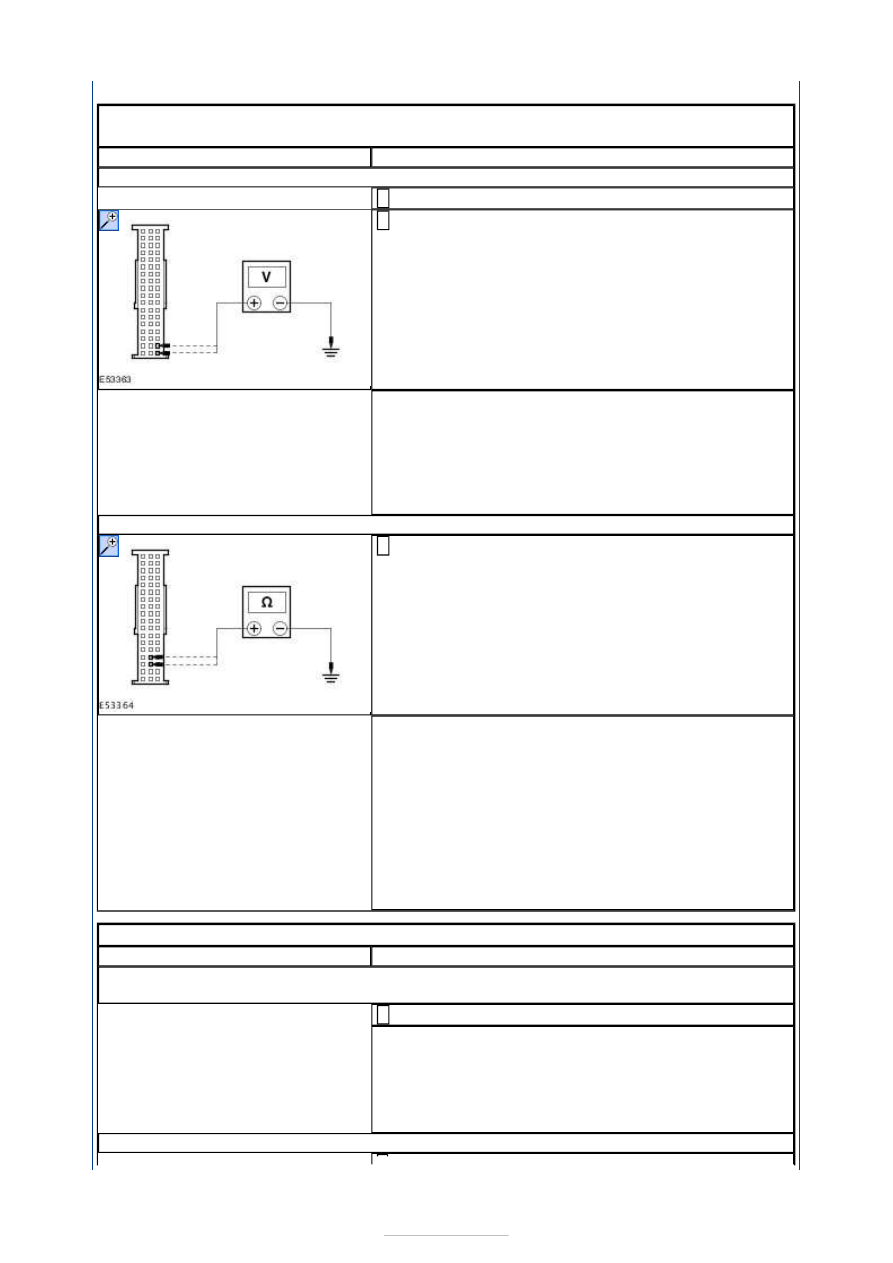
A1: CHECK FOR VOLTAGE AT THE PSE MODULE

Disconnect PSE Module C2MM01-A. 

Measure the voltage between the PSE module 
C2MM01-A pin 17, circuit SBP06H (BN/RD), harness 

side and ground; and the PSE module C2MM01-A pin 
18, circuit SBP06G (BN/RD), harness side and 
ground. 

Are the voltages greater than 10 volts? 
Yes 

GO to A2

.  

No 

REPAIR circuit SBP06H (BN/RD) or circuit SBP06G 
(BN/RD) as necessary. TEST the system for normal 
operation. 

A2: CHECK THE PSE MODULE GROUND CIRCUIT(S)

Measure the resistance between the PSE module 
C2MM01-A pin 33, circuit GD103E (BK/BU), harness 

side and ground; and the PSE module C2MM01-A pin 
34, circuit GD103F (BK/BU), harness side and 
ground. 

Are the resistances less than 1 ohm? 
Yes 

INSTALL a new PSE module.  
REFER to: 

Portable Support Electronics (PSE) Module


(415-01 Information and Entertainment System, 
Removal and Installation). 
TEST the system for normal operation. 

No 

REPAIR circuit GD103E (BK/BU) or circuit GD103F 
(BK/BU) as necessary. TEST the system for normal 
operation. 

PINPOINT TEST B : THE HANDSET BATTERY DOES NOT CHARGE 

TEST CONDITIONS

DETAILS/RESULTS/ACTIONS

B1: CHECK THE CELLULAR PHONE DISPLAY WHEN BEING USED OUTSIDE OF THE 
VEHICLE

Operate the cellular phone outside of the vehicle. 

Does the cellular phone display low battery? 
Yes 

GO to B2

.  

No 

CHECK the cellular phone battery. REFER to the 
cellular phone Owner's Guide. 

B2: CHECK THE BATTERY SYMBOL ON CELLULAR PHONE


Ignition switch in position II. 

INSTALL the cellular phone into the handset holder. Does 
the battery symbol flash? 
Yes 

Cellular phone battery charging correctly. WAIT for 
the cellular phone battery to charge. TEST the 
system for normal operation. 

No 

GO to B3

.  

B3: CHECK FOR VOLTAGE AT THE PSE MODULE

Disconnect PSE Module C2MM01-A. 

Measure the voltage between the PSE module 
C2MM01-A pin 17, circuit SBP06H (BN/RD), harness 

side and ground; and the PSE module C2MM01-A pin 
18, circuit SBP06G (BN/RD), harness side and 
ground. 

Are the voltages greater than 10 volts? 
Yes 

GO to B4

.  

No 

REPAIR circuit SBP06H (BN/RD) or circuit SBP06G 
(BN/RD) as necessary. TEST the system for normal 
operation. 

B4: CHECK THE PSE MODULE GROUND CIRCUIT(S)

Measure the resistance between the PSE module 
C2MM01-A pin 33, circuit GD103E (BK/BU), harness 

side and ground; and the PSE module C2MM01-A pin 
34, circuit GD103F (BK/BU), harness side and 
ground. 

Are the resistances less than 1 ohm? 
Yes 

For vehicles with voice control. 

GO to B5

.  

For vehicles without voice control. 

GO to B8

.  

No 

REPAIR circuit GD103E (BK/BU) or circuit GD103F 
(BK/BU) as necessary. TEST the system for normal 
operation. 

B5: CHECK FOR CHARGE VOLTAGE AT THE HANDSET HOLDER (WITH VOICE 
CONTROL)

Connect PSE Module C2MM01-A. 

Disconnect Handset Holder - with voice control 
C2MM17-A. 

Measure the voltage between the handset holder 
C2MM17-A pin 15, circuit CMM03B (VT), harness side 

and ground. 


Is the voltage greater than 10 volts? 
Yes 

GO to B6

.  

No 

NOTE: If the connector is damaged install a new 
harness. REPAIR the circuit CMM03B (VT). TEST the 
system for normal operation. 

B6: CHECK GROUND CIRCUIT RMM17B (GN/BU)

Measure the resistance between the handset holder 
C2MM17-A pin 8, circuit RMM17B (GN/BU), harness 

side and ground. 

Is the resistance less than 1 ohm? 
Yes 

GO to B7

.  

No 

REPAIR the circuit. TEST the system for normal 
operation. 

B7: CHECK FOR VOLTAGE AT CIRCUIT LMM17B (WH/BU)

Measure the voltage between the handset holder 
C2MM17-A pin 7, circuit LMM17B (WH/BU), harness 

side and ground. 

Is the voltage greater than 10 volts? 
Yes 

INSTALL a new PSE module.  
REFER to: 

Portable Support Electronics (PSE) Module


(415-01 Information and Entertainment System, 
Removal and Installation). 
TEST the system for normal operation. 

No 

REPAIR the circuit. TEST the system for normal 
operation. If the concern persists, INSTALL a new 
handset holder.  
REFER to: 

Handset Holder - Vehicles With: Voice 

Control

 (415-01 Information and Entertainment 

System, Removal and Installation). 
TEST the system for normal operation. 


B8: CHECK FOR CHARGE VOLTAGE AT THE HANDSET HOLDER (WITHOUT VOICE 
CONTROL)

Connect PSE Module C2MM01-A. 

Disconnect Handset Holder - without voice control 
C2MM17. 

Measure the voltage between the handset holder 
C2MM17 pin 15, circuit CMM03A (VT), harness side 

and ground. 

Is the voltage greater than 10 volts? 
Yes 

GO to B9

.  

No 

NOTE: If the connector is damaged install a new 
harness. REPAIR the circuit CMM03A (VT). TEST the 
system for normal operation. 

B9: CHECK GROUND CIRCUIT RMM17A (GN/BU)

Measure the resistance between the handset holder 
C2MM17 pin 8, circuit RMM17A (GN/BU), harness 

side and ground. 

Is the resistance less than 1 ohm? 
Yes 

GO to B10

.  

No 

REPAIR the circuit. TEST the system for normal 
operation. 

B10: CHECK FOR VOLTAGE AT CIRCUIT LMM17A (WH/BU)

Measure the voltage between the handset holder 
C2MM17 pin 7, circuit LMM17A (WH/BU), harness 

side and ground. 

Is the voltage greater than 10 volts? 
Yes 

INSTALL a new PSE module.  
REFER to: 

Portable Support Electronics (PSE) Module


(415-01 Information and Entertainment System, 
Removal and Installation). 
TEST the system for normal operation. 

No 

REPAIR the circuit. TEST the system for normal 


Content   ..  729  730  731  732   ..