Ford Galaxy / Ford S-MAX. Manual - part 729
 

  Index      Ford     Ford Galaxy / Ford S-MAX - service repair manual 2006 year


Search            


Content   ..  727  728  729  730   ..


Ford Galaxy / Ford S-MAX. Manual - part 729


Is the resistance less than 1 ohm? 
Yes 

GO to M24

.  

No 

REPAIR circuit(s) RMR16B (BK/BU) or RMR16A 
(BK/BU). TEST the system for normal operation. 

M24: CHECK CIRCUITS VMR16B (GY/BK) AND VMR16A (GY/BK) FOR OPEN

Measure the resistance between the DVD player C2MR-
D pin 19, circuit VMR16B (GY/BK), harness side and 

video display C33-U pin 9, circuit VMR16A (GY/BK), 
harness side. 

Is the resistance less than 1 ohm? 
Yes 

GO to M25

.  

No 

REPAIR circuit(s) VMR16B (GY/BK) or VMR16A 
(GY/BK). TEST the system for normal operation. 

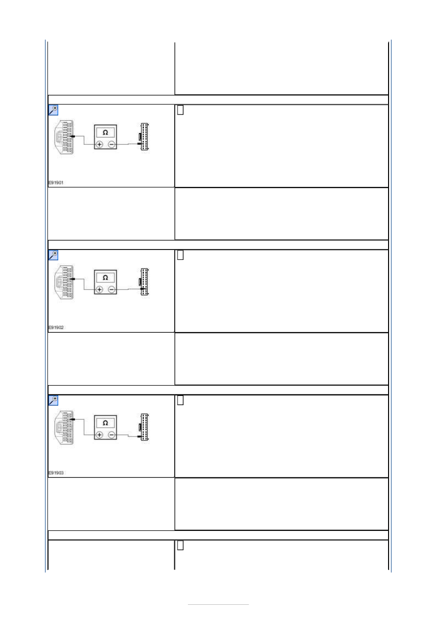
M25: CHECK CIRCUITS VMR17B (VT/GN) AND VMR17A (VT/GN) FOR OPEN

Measure the resistance between the DVD player C2MR-
D pin 20, circuit VMR17B (VT/GN), harness side and 

video display C33-U pin 20, circuit VMR17A (VT/GN), 
harness side. 

Is the resistance less than 1 ohm? 
Yes 

GO to M26

.  

No 

REPAIR circuit(s) VMR17B (VT/GN) or VMR17A 
(VT/GN). TEST the system for normal operation. 

M26: CHECK CIRCUITS VMR19B (WH/VT) AND VMR19A (WH/VT) FOR OPEN

Measure the resistance between the DVD player C2MR-
D pin 22, circuit VMR19B (WH/VT), harness side and 

video display C33-U pin 10, circuit VMR19A (WH/VT), 
harness side. 

Is the resistance less than 1 ohm? 
Yes 

GO to M27

.  

No 

REPAIR circuit(s) VMR19B (WH/VT) or VMR19A 
(WH/VT). TEST the system for normal operation. 

M27: CHECK CIRCUITS VMR18B (YE/GN) AND VMR19A (YE/GN) FOR OPEN

Measure the resistance between the DVD player C2MR-
D pin 23, circuit VMR18B (YE/GN), harness side and 

video display C33-U pin 21, circuit VMR19A (YE/GN), 


harness side. 

Is the resistance less than 1 ohm? 
Yes 

GO to M28

.  

No 

REPAIR circuit(s) VMR18B (YE/GN) or VMR19A 
(YE/GN). TEST the system for normal operation. 

M28: CHECK CIRCUITS RMR27E (BN/VT), RMR27B (BN/VT), RMR27A (BN/VT), 
RMR27C AND RMR27D FOR OPEN

Measure the resistance between the following DVD 
player C2MR-D pins, harness side and video display 

C33-U pins, harness side. 

C2MR-D pin 24, circuit RMR27E (BN/VT) and C33-U 
pin 14, circuit RMR27A (BN/VT). 

C2MR-D pin 24, circuit RMR27E (BN/VT) and C33-U 
pin 19, circuit RMR27D. 

Are the resistances less than 1 ohm? 
Yes 

GO to M29

.  

No 

REPAIR circuit(s) RMR27E (BN/VT), RMR27B (BN/VT), 
RMR27A (BN/VT), RMR27C or RMR27D. TEST the 
system for normal operation. 

M29: CHECK CIRCUITS VMR23B (GN/OG) AND VMR23A (GN/OG) FOR OPEN

Connect DVD Player C2MR-D. 

Disconnect DVD Player C2MR-C. 

Measure the resistance between the DVD player C2MR-
C pin 7, circuit VMR23B (GN/OG), harness side and 

video display C33-U pin 6, circuit VMR23A (GN/OG), 
harness side. 

Is the resistance less than 1 ohm? 
Yes 

GO to M30

.  

No 

REPAIR circuit(s) VMR23B (GN/OG) and VMR23A 
(GN/OG). TEST the system for normal operation. 

M30: CHECK CIRCUITS DMR22B AND DMR22A FOR OPEN

Measure the resistance between the DVD player C2MR-
C pin 21, circuit DMR22B, harness side and video 

display C33-U pin 17, circuit VMR24A (GY/VT), harness 
side. 


Is the resistance less than 1 ohm? 
Yes 

GO to M31

.  

No 

REPAIR circuit(s) DMR22B and DMR22A. TEST the 
system for normal operation. 

M31: CHECK CIRCUITS VMR20B (BN/WH) AND VMR20A (BN/WH) FOR OPEN

Measure the resistance between the DVD player C2MR-
C pin 4, circuit VMR20B (BN/WH), harness side and 

video display C33-U pin 7, circuit VMR20A (BN/WH), 
harness side. 

Is the resistance less than 1 ohm? 
Yes 

GO to M32

.  

No 

REPAIR the circuit. TEST the system for normal 
operation. 

M32: CHECK CIRCUITS VMR21B (BU/BN) AND VMR21A (BU/BN) FOR OPEN

Measure the resistance between the DVD player C2MR-
C pin 18, circuit VMR21B (BU/BN), harness side and 

video display C33-U pin 18, circuit VMR21A (BU/BN), 
harness side. 

Is the resistance less than 1 ohm? 
Yes 

GO to M33

.  

No 

REPAIR circuit(s) VMR21B (BU/BN) or VMR21A 
(BU/BN). TEST the system for normal operation. 

M33: CHECK CIRCUITS DMR20B AND DMR20A FOR OPEN

Measure the resistance between the DVD player C2MR-
C pin 19, circuit DMR20B, harness side and video 

display C33-U pin 8, circuit DMR20A, harness side. 


Is the resistance less than 1 ohm? 
Yes 

CHECK the DVD player. GO to Pinpoint Test 

L. 


No 

REPAIR circuits DMR20B or DMR20A. TEST the system 
for normal operation. 


Content   ..  727  728  729  730   ..