Ford Galaxy / Ford S-MAX. Manual - part 727
 

  Index      Ford     Ford Galaxy / Ford S-MAX - service repair manual 2006 year


Search            


Content   ..  725  726  727  728   ..


Ford Galaxy / Ford S-MAX. Manual - part 727


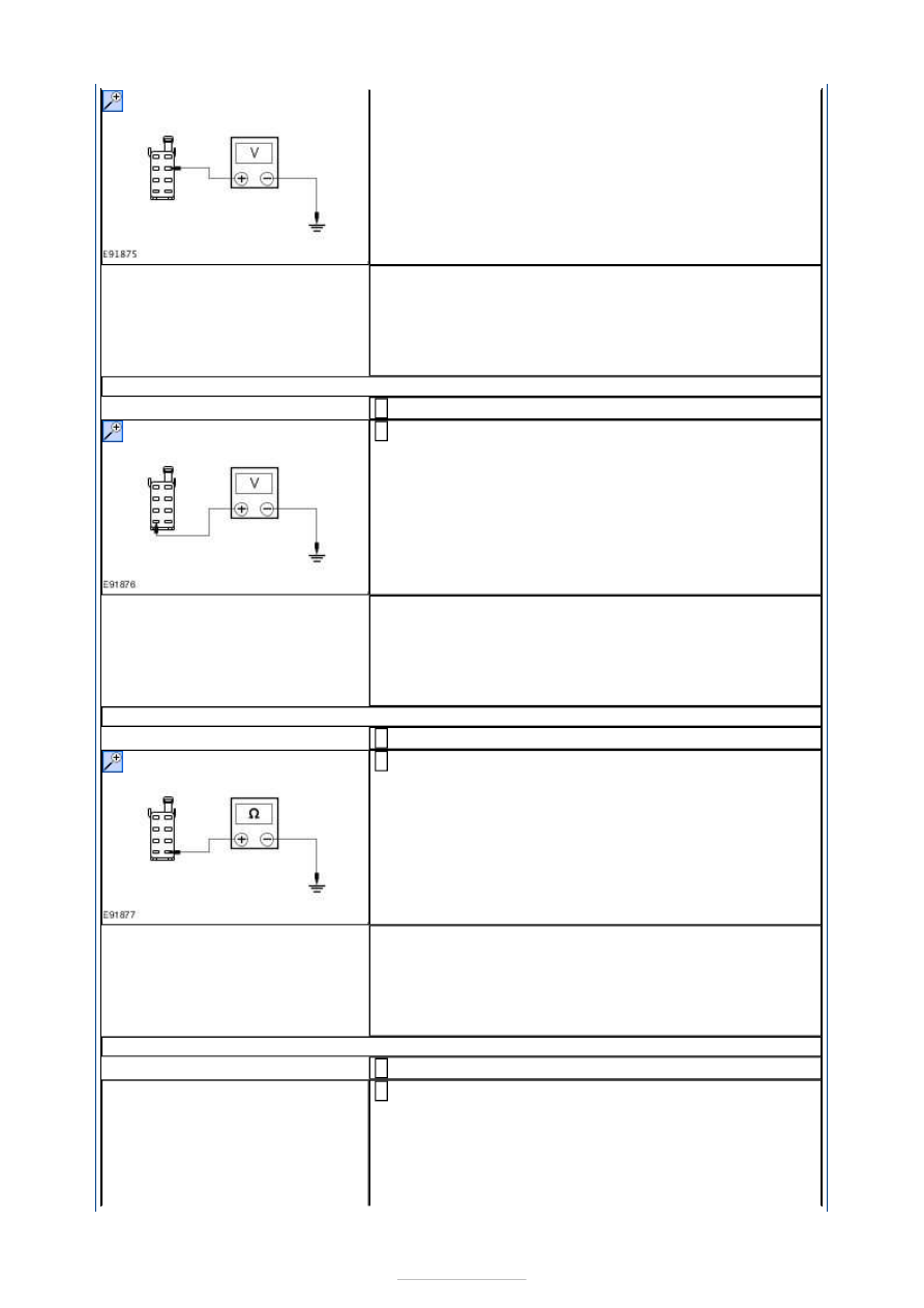
ground. 

Is the voltage greater than 10 volts? 
Yes 

GO to L2

.  

No 

REPAIR circuit C_SBR05D (GY/RD). TEST the system 
for normal operation. 

L2: CHECK THE DVD PLAYER FOR SWITCHED POWER

Ignition switch in position II. 

Measure the voltage between the DVD player C2MR-A 
pin 7, circuit A_CBP04B (VT), harness side and ground. 

Is the voltage greater than 10 volts? 
Yes 

GO to L3

.  

No 

REPAIR circuit A_CBP04B (VT). TEST the system for 
normal operation. 

L3: CHECK THE DVD PLAYER FOR GROUND

Ignition switch in position 0. 

Measure the resistance between the DVD player C2MR-
A pin 8, circuit GD151L (BK/GN), harness side and 

ground. 

Is the resistance less than 1 ohm? 
Yes 

GO to L4

.  

No 

REPAIR circuit GD151L (BK/GN). TEST the system for 
normal operation. 

L4: CHECK THE DVD PLAYER ILLUMINATION CIRCUIT FOR POWER

Turn the multi-function switch to the on position. 

Measure the voltage between the DVD player C2MR-A 
pin 6, circuit A_CLN17B (BN), harness side and 

ground. 


Is the voltage greater than 10 volts? 
Yes 

INSTALL a new DVD player.  
REFER to: Digital Versatile Disc (DVD) Player (415-01, 
Removal and Installation). 
TEST the system for normal operation. 

No 

REPAIR circuit GLN17B (BN). TEST the system for 
normal operation. 

PINPOINT TEST M : THE VIDEO SYSTEM IS INOPERATIVE/DOES NOT 
OPERATE CORRECTLY 

WARNING: Do not attempt to open or repair a video display as there are internal 

voltages in excess of 2000 volts. Failure to follow this instruction may result in personal 
injury. 

TEST CONDITIONS

DETAILS/RESULTS/ACTIONS

M1: CHECK THE OPERATION OF THE VIDEO DISPLAY

Change the head restraints/video displays between the 
two front seats. 

Has the concern moved with the video display? 
Yes 

INSTALL a new head restraint/video display. TEST the 
system for normal operation. 

No 

For concern with the left-hand video display, 

GO to M2

For concern with the right-hand video display, 

GO to 

M18

.  

M2: CHECK CIRCUITS CMR13B (WH/GN) AND CMR13A (WH/GN) FOR OPEN

Disconnect DVD player C2MR-D. 

Disconnect Video display C33-T. 

Measure the resistance between the DVD player C2MR-
D pin 1, circuit CMR13B (WH/GN), harness side and 

video display C33-T pin 3, circuit GMR13A (GN/WH), 
harness side. 

Is the resistance less than 1 ohm? 
Yes 

GO to M3

.  

No 

REPAIR circuit(s) GMR13B (WH/GN) or GMR13A 
(WH/GN). TEST the system for normal operation. 

M3: CHECK CIRCUITS LMR01B (BU/WH) AND LMR01A (BU/WH) FOR OPEN

Measure the resistance between the DVD player C2MR-


D pin 2, circuit LMR01B (BU/WH), harness side and 
video display C33-T pin 4, circuit LMR01A (BU/WH), 
harness side. 

Is the resistance less than 1 ohm? 
Yes 

GO to M4

.  

No 

REPAIR circuit(s) LMR01B (BU/WH) or LMR01A 
(BU/WH). TEST the system for normal operation. 

M4: CHECK CIRCUITS VMR10B (GY/OG) AND VMR10A (GY/OG) FOR OPEN

Measure the resistance between the DVD player C2MR-
D pin 3, circuit VMR10B (GY/OG), harness side and 

video display C33-T pin 5, circuit VMR10A (GY/OG), 
harness side. 

Is the resistance less than 1 ohm? 
Yes 

GO to M5

.  

No 

REPAIR circuit(s) VMR10B (GY/OG) or VMR10A 
(GY/OG). TEST the system for normal operation. 

M5: CHECK CIRCUITS VMR11B (VT/OG) AND VMR11A (VT/OG) FOR OPEN

Measure the resistance between the DVD player C2MR-
D pin 4, circuit VMR11B (VT/OG), harness side and 

video display C33-T pin 16, circuit VMR11A (VT/OG), 
harness side. 

Is the resistance less than 1 ohm? 
Yes 

GO to M6

.  

No 

REPAIR circuit(s) VMR11B (VT/OG) or VMR11A 
(VT/OG). TEST the system for normal operation. 

M6: CHECK CIRCUITS VMR12B (GY/VT) AND VMR12A (GY/VT) FOR OPEN

Measure the resistance between the DVD player C2MR-
D pin 5, circuit VMR12B (GY/VT), harness side and 

video display C33-T pin 11, circuit VMR11A (GY/VT), 
harness side. 


Is the resistance less than 1 ohm? 
Yes 

GO to M7

.  

No 

Repair circuit(s) VMR11B (GY/VT) or VMR11A (GY/VT). 
TEST the system for normal operation. 

M7: CHECK CIRCUITS RMR02B (BK/BU) AND RMR02A (BK/BU) FOR OPEN

Measure the resistance between the DVD player C2MR-
D pin 6, circuit RMR02B (BK/BU), harness side and 

video display C33-T pin 22, circuit RMR02A (BK/BU), 
harness side. 

Is the resistance less than 1 ohm? 
Yes 

GO to M8

.  

No 

REPAIR circuits RMR02B (BK/BU) or RMR02A (BK/BU). 
TEST the system for normal operation. 

M8: CHECK CIRCUITS VMR02B (GY/BK) AND VMR02A (GY/BK) FOR OPEN

Measure the resistance between the DVD player C2MR-
D pin 7, circuit VMR02B (GY/BK), harness side and 

video display C33-T pin 9, circuit VMR02A (GY/BK), 
harness side. 

Is the resistance less than 1 ohm? 
Yes 

GO to M9

.  

No 

REPAIR circuit(s) VMR02B (GY/BK) or VMR02A 
(GY/BK). TEST the system for normal operation. 

M9: CHECK CIRCUITS VMR03B (GY/VT) AND VMR03A (GY/VT) FOR OPEN

Measure the resistance between the DVD player C2MR-
D pin 8, circuit VMR03B (GY/VT), harness side and 

video display C33-T pin 20, circuit VMR03A (GY/VT), 
harness side. 

Is the resistance less than 1 ohm? 
Yes 

GO to M10

.  

No 

REPAIR circuit(s) VMR03B (GY/VT) or VMR03A (GY/VT). 
TEST the system for normal operation. 

M10: CHECK CIRCUITS VME05B (GY/WH) AND VME05A (GY/WH) FOR OPEN

Measure the resistance between the DVD player C2MR-
D pin 10, circuit VME05B (GY/WH), harness side and 

video display C33-T pin 10, circuit VME05A (GY/WH), 


Content   ..  725  726  727  728   ..