Ford Galaxy / Ford S-MAX. Manual - part 726
 

  Index      Ford     Ford Galaxy / Ford S-MAX - service repair manual 2006 year


Search            


Content   ..  724  725  726  727   ..


Ford Galaxy / Ford S-MAX. Manual - part 726


GO to H3

.  

No 

REPAIR the circuit(s) in question. TEST the system 
for normal operation. 

H3: CHECK THE INOPERATIVE TWEETER SPEAKER(S) CIRCUIT FOR SHORT TO 
GROUND

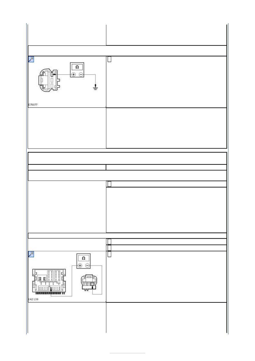
Measure the resistance between the following rear 
tweeter speaker pins, harness side and ground: 

Left-hand side C7ME39 pin 1, circuit VME39A 
(GN/BN).  
Right-hand side C8ME4D pin 1, circuit VME40A 
(BN/WH). 

Is the resistance greater than 10,000 ohms (open 
circuit)? 
Yes 

INSTALL a new tweeter speaker. TEST the system for 
normal operation. 

No 

REPAIR the circuit(s) in question. TEST the system 
for normal operation. 

PINPOINT TEST I : THE AUDIO CONTROL SWITCH IS INOPERATIVE/DOES 
NOT OPERATE CORRECTLY 

TEST CONDITIONS

DETAILS/RESULTS/ACTIONS

I1: CHECK THE AUDIO UNIT OPERATES CORRECTLY USING THE AUDIO UNIT 
CONTROLS

Operate the audio unit using the audio unit controls. 

Does the audio unit operate correctly using the audio unit 
controls? 
Yes 

GO to I2

.  

No 

INSTALL a new audio unit.  
REFER to: Audio Unit (415-01 Information and 
Entertainment System, Removal and Installation). 
TEST the system for normal operation. 

I2: CHECK CIRCUIT VME14A (GY/YE) FOR OPEN

Disconnect Audio Unit C2ME03B. 

Disconnect Clockspring C2LS41. 

Measure the resistance between the audio unit 
C2ME03B pin 6, circuit VME14A (GY/YE) harness side 

and the clockspring C2LS41 pin 11, circuit VME14A 
(GY/YE) harness side. 

Is the resistance less than 1 ohm? 
Yes 

GO to I3

.  

No 

REPAIR the circuit. TEST the system for normal 


operation. 

I3: CHECK CIRCUIT RME24A (BU/WH) FOR OPEN

Measure the resistance between the audio unit 
C2ME03B pin 8, circuit RME24A (BU/WH) harness 

side and the clockspring CME14 pin 2, circuit RME24B 
(BU/WH) harness side. 

Is the resistance less than 1 ohm? 
Yes 

INSTALL a new audio control switch. TEST the system 
for normal operation. If the concern persists, 
INSTALL a new audio unit.  
REFER to: Audio Unit (415-01 Information and 
Entertainment System, Removal and Installation). 

No 

REPAIR the circuit. TEST the system for normal 
operation. 

PINPOINT TEST J : THE CD CHANGER IS INOPERATIVE/DOES NOT 
OPERATE CORRECTLY 

TEST CONDITIONS

DETAILS/RESULTS/ACTIONS

J1: CHECK THE CD CHANGER FOR VOLTAGE

Disconnect CD changer C2ME27. 

Measure the voltage between the CD changer 
C2ME27 pin 1, circuit SBR05AWA (GY/RD), harness 

side and ground. 

Is the voltage greater than 10 volts? 
Yes 

GO to J2

.  

No 

REPAIR circuit SBR05AWA (GY/RD). TEST the system 
for normal operation. 

J2: CHECK THE CD CHANGER FOR GROUND

Measure the resistance between the CD changer 
C2ME27 pin 6, circuit GD135M (BK/GY), harness side 

and ground. 

Is the resistance less than 1 ohm? 
Yes 

GO to J3

.  

No 


REPAIR the circuit. TEST the system for normal 
operation. 

J3: CHECK THE CD CHANGER TO AUDIO UNIT CIRCUIT(S) FOR OPEN

Disconnect Audio Unit C2ME03B. 

Measure the resistance between the following CD 
changer circuits and the audio unit circuit(s): 

CD changer C2ME27 pin 3, circuit VME15B 
(GN/BK), harness side and audio unit C2ME03B pin 
3, circuit VME15A (GN/BK), harness side. 

CD changer C2ME27 pin 8, circuit RME15B 
(VT/GY), harness side and audio unit C2ME03B pin 
9, circuit RME15A (VT/GY), harness side. 

CD changer C2ME27 pin 4, circuit VME16B 
(GY/RD), harness side and audio unit C2ME03B pin 
4, circuit RME16A (GY/RD), harness side. 

CD changer C2ME27 pin 9, circuit RME16B 
(YE/GY), harness side and audio unit C2ME03B pin 
10, circuit RME16A (YE/GY), harness side. 

Are the resistances less than 1 ohm? 
Yes 

INSTALL a new CD changer. TEST the system for 
normal operation. 

No 

REPAIR the circuits as necessary. TEST the system 
for normal operation. If the concern persists, 
INSTALL a new audio unit.  

PINPOINT TEST K : THE AUXILIARY INPUT DEVICE IS 
INOPERATIVE/DOES NOT OPERATE CORRECTLY 

TEST CONDITIONS

DETAILS/RESULTS/ACTIONS

K1: CHECK THE OPERATION OF THE AUXILIARY INPUT DEVICE

Operate the auxiliary input device outside of the 
vehicle. 

Does the auxiliary input device operate outside of the 
vehicle? 
Yes 

GO to K3

.  

No 

REFER to the auxiliary input device Owner Guide. 

K2: CHECK THE AUXILIARY INPUT DEVICE CONNECTOR

Check the auxiliary input device connector for signs 
of damage or debris. 

Is the auxiliary input device connector free of damage 
and debris? 
Yes 

GO to K3

.  

No 

INSTALL a new auxiliary input device connector. TEST 
the system for normal operation. 

K3: CHECK CIRCUIT VME37A (BU/RD) FOR OPEN

Disconnect Audio Unit C2ME03C. 

Measure the resistance between the audio unit 
C2ME03C pin 5, circuit VME37A (BU/RD), harness 

side and auxiliary input device C2ME37 pin 4, circuit 


VME37A (BU/RD), harness side. 

Is the resistance less than 1 ohm? 
Yes 

GO to K4

.  

No 

REPAIR circuit VME37A (BU/RD). TEST the system for 
normal operation. 

K4: CHECK CIRCUIT VME38A (BN/RD) FOR OPEN

Measure the resistance between the audio unit 
C2ME03C pin 11, circuit VME38A (BN/RD), harness 

side and auxiliary input device C2ME37 pin 1, circuit 
VME38A (BN/RD), harness side. 

Is the resistance less than 1 ohm? 
Yes 

GO to K5

.  

No 

REPAIR circuit VME38A (BN/RD). TEST the system for 
normal operation. 

K5: CHECK CIRCUIT DME37G (OG/GN) FOR GROUND

Measure the resistance between the audio unit 
C2ME03C pin 6, circuit DME37G (OG/GN), harness 

side and ground. 

Is the resistance less than 1 ohm? 
Yes 

INSTALL a new audio unit. TEST the system for 
normal operation. 

No 

REPAIR circuit DME37G (OG/GN). TEST the system 
for normal operation. 

PINPOINT TEST L : THE DIGITAL VERSATILE DISC (DVD) PLAYER IS 
INOPERATIVE/DOES NOT OPERATE CORRECTLY 

TEST CONDITIONS

DETAILS/RESULTS/ACTIONS

L1: CHECK THE DVD PLAYER FOR POWER

Disconnect DVD Player C2MR-A. 

Measure the voltage between the DVD player C2MR-A 
pin 4, circuit C_SBR05D (GY/RD), harness side and 


Content   ..  724  725  726  727   ..