Ford Galaxy / Ford S-MAX. Manual - part 724
 

  Index      Ford     Ford Galaxy / Ford S-MAX - service repair manual 2006 year


Search            


Content   ..  722  723  724  725   ..


Ford Galaxy / Ford S-MAX. Manual - part 724


Is the resistance greater than 10,000 ohms (open 
circuit)? 
Yes 

CLEAN and TIGHTEN the ground connections at the 
base of the antenna and battery negative cable to 
the body. If concern the persists, 

GO to B4

.  

No 

INSTALL a new antenna cable. TEST the system for 
normal operation. If the concern persists, INSTALL 
a new audio unit.  
REFER to: Audio Unit (415-01 Information and 
Entertainment System, Removal and Installation). 

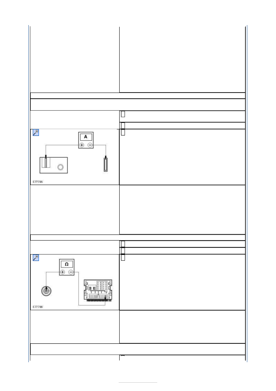
B4: CHECK THE CURRENT DRAW OF THE SECONDARY ANTENNA CABLE AMPLIFIER

NOTE: The secondary antenna cable amplifier is located under the headliner above the 
left-rear quarter window glass. 

Disconnect Secondary Antenna Cable Amplifier 
Power Supply. 

Switch the audio unit on. 

Measure the amperage between the secondary 
antenna cable amplifier power supply electrical 

connector and the power supply connection on the 
secondary antenna cable amplifier. 

Is the amperage between 20 and 70 milliamps? 
Yes 

GO to B5

.  

No 

Clean and TIGHTEN the secondary antenna cable 
amplifier ground connection. TEST the system for 
normal operation. If the concern persists, INSTALL 
a new secondary antenna cable amplifier. TEST the 
system for normal operation. 

B5: CHECK THE SECONDARY ANTENNA CABLE FOR OPEN

Disconnect Audio Unit C2ME03B. 

Disconnect Secondary Antenna Cable. 

Measure the resistance between the audio unit 
electrical connector C2ME03B, circuit CME36A 

(GN/VT), harness side and the secondary antenna 
cable connector, harness side. 

Is the resistance less than 1 ohm? 
Yes 

GO to B6

.  

No 

INSTALL a new secondary antenna. TEST the 
system for normal operation. 

B6: CHECK THE SECONDARY ANTENNA CABLE AMPLIFIER TO LEFT-REAR QUARTER 
GLASS WIRING HARNESS FOR OPEN


Disconnect Secondary Antenna Cable Amplifier to 
Left-rear Quarter Glass wiring harness (at both 

ends). 

Measure the resistances between the following 
secondary antenna cable amplifier to left-rear 

quarter glass wiring harness electrical connectors. 

Secondary antenna cable amplifier connector pin 
1, harness side and left-rear quarter glass 
connector pin A, harness side. 

Secondary antenna cable amplifier connector pin 
2, harness side and left-rear quarter glass 
connector pin B, harness side. 

Are the resistances less than 1 ohm? 
Yes 

INSTALL a new left-rear quarter window glass. 
TEST the system for normal operation. 

No 

INSTALL a new secondary antenna cable amplifier 
to left-rear quarter glass wiring harness. TEST the 
system for normal operation. 

PINPOINT TEST C : POOR QUALITY/DISTORTED SOUND FROM ONE OR 
MORE MAIN SPEAKERS (NOT ALL SPEAKERS) 

TEST CONDITIONS

DETAILS/RESULTS/ACTIONS

C1: CHECK THE SPEAKER RESISTANCE

Disconnect Affected Speaker. 

Measure the resistance between the following affected 
speaker pins, component side. 

(Front speakers) pin 1 and pin 4.  
(Third row speakers) pins 1 and 2 (if equipped).  
(Rear speakers) pin 1 and pin 4. 

Is the resistance approximately 4.0 ohms? 
Yes 

GO to C2

.  

No 

INSTALL a new speaker. TEST the system for normal 
operation. 

C2: CHECK SPEAKER INPUT FOR SHORT TO GROUND

Disconnect Audio Unit CME03A. 

Measure the resistance between affected speaker 
connector pin 1, harness side and ground. 

Is the resistance greater than 10,000 ohms (open circuit)? 
Yes 

GO to C3

.  


No 

REPAIR the speaker input circuit. TEST the system for 
normal operation. 

C3: CHECK SPEAKER RETURN FOR SHORT TO GROUND

Measure the resistance between the following affected 
speaker connector pins, harness side and ground: 

(Front speakers) pin 4 and ground.  
(Third row speakers) pin 2 and ground (if equipped).  
(Rear speakers) pin 4 and ground. 

Is the resistance greater than 10,000 ohms (open circuit)? 
Yes 

INSTALL a new speaker. TEST the system for normal 
operation. If the concern persists, INSTALL a new audio 
unit.  
REFER to: Audio Unit (415-01 Information and 
Entertainment System, Removal and Installation). 

No 

REPAIR the speaker return circuit. TEST the system for 
normal operation. 

PINPOINT TEST D : POOR QUALITY/DISTORTED SOUND FROM ONE OR 
MORE FRONT TWEETER SPEAKERS (NOT ALL SPEAKERS) 

TEST CONDITIONS

DETAILS/RESULTS/ACTIONS

D1: CHECK THE SPEAKER INPUT FOR SHORT TO GROUND

Disconnect Audio Unit C2ME03D. 

Disconnect Affected Front Tweeter Speaker. 

Measure the resistance between affected front 
tweeter speaker connector pin 1, harness side and 

ground. 

Is the resistance greater than 10,000 ohms (open 
circuit)? 
Yes 

GO to D2

.  

No 

REPAIR the speaker input circuit. TEST the system 
for normal operation. 

D2: CHECK THE SPEAKER RETURN FOR SHORT TO GROUND

Measure the resistance between affected front 
tweeter speaker connector pin 3, harness side and 

ground. 


Is the resistance greater than 10,000 ohms (open 
circuit)? 
Yes 

INSTALL a new tweeter speaker. TEST the system 
for normal operation. 

No 

REPAIR the speaker return circuit. TEST the system 
for normal operation. 

PINPOINT TEST E : POOR QUALITY/DISTORTED SOUND FROM ONE OR 
MORE REAR TWEETER SPEAKERS (NOT ALL SPEAKERS) 

TEST CONDITIONS

DETAILS/RESULTS/ACTIONS

E1: CHECK THE SPEAKER INPUT FOR SHORT TO GROUND

Disconnect Affected Rear Tweeter Speaker. 

Disconnect Rear Speaker On Affected Rear Tweeter 
Speaker Side. 

Measure the resistance between affected rear 
tweeter speaker connector pin 1, harness side and 

ground. 

Is the resistance greater than 10,000 ohms (open 
circuit)? 
Yes 

GO to E2

.  

No 

REPAIR the speaker input circuit. TEST the system 
for normal operation. 

E2: CHECK THE SPEAKER OUTPUT FOR SHORT TO GROUND

Measure the resistance between affected rear 
tweeter speaker connector pin 3, harness side and 

ground. 

Is the resistance greater than 10,000 ohms (open 
circuit)? 
Yes 

INSTALL a new tweeter speaker. TEST the system 
for normal operation. 

No 

REPAIR the speaker output circuit. TEST the system 
for normal operation. 

PINPOINT TEST F : NO SOUND FROM ONE OR MORE OF THE MAIN 
SPEAKERS (NOT ALL SPEAKERS) 

TEST CONDITIONS

DETAILS/RESULTS/ACTIONS

F1: CHECK THE SPEAKER RESISTANCE

Disconnect Affected Speaker. 


Content   ..  722  723  724  725   ..