Ford Galaxy / Ford S-MAX. Manual - part 723
 

  Index      Ford     Ford Galaxy / Ford S-MAX - service repair manual 2006 year


Search            


Content   ..  721  722  723  724   ..


Ford Galaxy / Ford S-MAX. Manual - part 723


4. 4. If the cause is not evident after the Self-Diagnostic Mode, connect the 

Ford 

approved diagnostic tool

 to the data link connector (DLC). 

5. 5. Retrieve the Diagnostic Trouble Code (DTC)s and refer to the DTC Index Chart. 

Self-Diagnostic Mode - High Series Audio Unit 

NOTE: The audio unit must be in radio mode before entering the Self-Diagnostic Mode. 

1. 1. To enter the audio unit Self-Diagnostic Mode, switch the audio unit ON. Within four 

seconds press the preset buttons 3 and 6 together. 

2. 2. Release the preset buttons 3 and 6 and the audio unit will enter the Self-Diagnostic 

Mode. 

3. 3. To exit the Self-Diagnostic Mode, switch the audio unit OFF. 

Self-Diagnostic Mode 

4. 4. If the cause is not evident after the Self-Diagnostic Mode, connect the 

Ford 

approved diagnostic tool

 to the data link connector (DLC). 

5. 5. Retrieve the Diagnostic Trouble Code (DTC)s and refer to the DTC Index Chart. 

Diagnostic Trouble Code (DTC) Index Chart 

5. XX.X (frequency) SEEKING

Antenna cable

6. XXXXXXXX (name of radio station)

Active FM frequency radio station found 

(audible for 2 seconds)

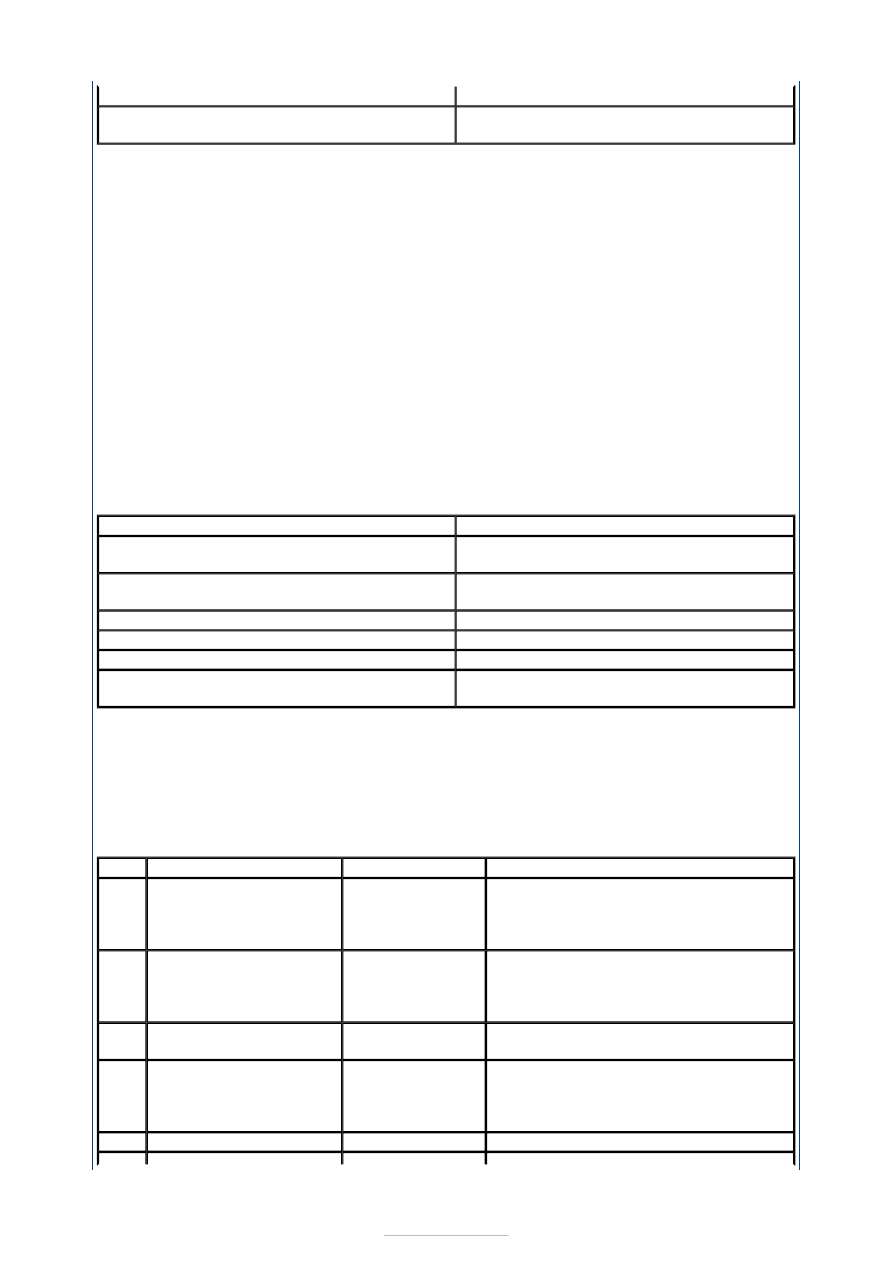
Message Displayed

Circuit Tested

1. 4CH LF for four channel system 2CH LF for 

two channel system

Left hand front speaker circuit

2. 4CH RF for four channel system 2CH RF for 

two channel system

Right hand front speaker circuit

3. 4CH LR for four channel system

Left hand rear speaker circuit

4. 4CH RR for four channel system

Right hand rear speaker circuit

5. XX.X (frequency) SEEKING

Antenna cable

6. XXXXXXXX (name of radio station)

Active FM frequency radio station found 

(audible for 2 seconds)

DTC

Description/Condition

Possible Source

Action

B1342 Audio unit internal failure

Audio unit

INSTALL a new audio unit.  

REFER to: Audio Unit (415-01 

Information and Entertainment System, 

Removal and Installation). 

B2403 CD player internal failure

Audio unit

INSTALL a new audio unit.  

REFER to: Audio Unit (415-01 

Information and Entertainment System, 

Removal and Installation). 

B2404

Audio control switch 

circuit failure

Audio control 

switch

GO to Pinpoint Test 

I. 

B2406 CD player internal failure

Audio unit

INSTALL a new audio unit.  

REFER to: Audio Unit (415-01 

Information and Entertainment System, 

Removal and Installation). 

B2408 Speaker line short circuit

Speaker(s)

GO to Pinpoint Test 

C. 

1. 1. If the cause is still evident, refer to the Symptom Chart. 

Symptom Chart 

B2409 AM receiving signal error

Antenna cable

GO to Pinpoint Test 

B. 

B2410 FM receiving signal error

Antenna cable

GO to Pinpoint Test 

B. 

B2477

Module configuration 

failure

Audio unit and 

central junction 

box (CJB)

REFER to the Ford approved diagnostic 

tool.

P1628

Module ignition supply 

input

CJB

REFER to the Ford approved diagnostic 

tool.

Symptom

Possible Sources

Action

The audio unit is 
inoperative/does not operate 
correctly

Circuit(s). 
Audio unit. 

*
*

GO to Pinpoint Test 

A. 


*

The display is blank - radio 
and CD player operate

Audio unit. 

*

INSTALL a new audio unit.  

REFER to: Audio Unit (415-01 
Information and Entertainment System, 
Removal and Installation). 

*

Poor reception

Antenna. 
Antenna cable. 
Audio unit. 

*
*
*

GO to Pinpoint Test 

B. 


*

Poor quality/distorted sound 
from one or more speakers 
(not all speakers)

Speaker(s). 
Circuit(s). 
Audio unit. 

*
*
*

For concern with the main speakers, GO 

to Pinpoint Test 

C. 


For concern with the front tweeter 

speakers, GO to Pinpoint Test 

D. 


For concern with the rear tweeter 

speakers, GO to Pinpoint Test 

E. 


*

*

*

No sound from all speakers

Audio unit. 

*

INSTALL a new audio unit.  

REFER to: Audio Unit (415-01 
Information and Entertainment System, 
Removal and Installation). 
TEST the system for normal operation. 

*

No sound from one or more of 
the speakers (not all 
speakers)

Speaker(s). 
Circuit(s). 
Audio unit. 

*
*
*

For concern with the main speakers, GO 

to Pinpoint Test 

F. 


For concern with the front tweeter 

speakers, GO to Pinpoint Test 

G. 


For concern with the rear tweeter 

speakers, GO to Pinpoint Test 

H. 


*

*

*

The auxiliary audio control is 
inoperative/does not operate 
correctly.

Circuit(s). 
Auxiliary audio 

control switch. 

Audio unit. 

*
*

*

GO to Pinpoint Test 

I. 


*

The CD changer is 
inoperative/does not operate 
correctly

Circuit(s). 
CD changer. 

*
*

GO to Pinpoint Test 

J. 


*

The audio unit illumination is 
inoperative

Circuit(s). 
Audio unit. 
Genetic electronic 

module (GEM). 

*
*
*

REFER to: Instrument Cluster and Panel 

Illumination (413-00 Instrument Cluster 
and Panel Illumination, Diagnosis and 
Testing). 

*

The auxiliary input device is 
inoperative/does not operate 
correctly

Auxiliary input 

device. 

*

REFER the customer to the auxiliary 

input source supplier. 

*

Circuit(s). 
Audio unit. 

*
*

GO to Pinpoint Test 

K. 


*

The DVD player is 
inoperative/does not operate 
correctly

Contaminated 

DVD disc(s). 

*

CLEAN the DVD disc(s) using lint free 

material. TEST the system for normal 
operation. 

*

Pinpoint Tests 

NOTE: Use a digital multimeter for all electrical measurements. 

Circuit(s). 
DVD player. 

*
*

GO to Pinpoint Test 

L. 


*

The video display is 
inoperative/does not operate 
correctly

Contaminated 

DVD disc(s). 

*

CLEAN the DVD disc(s) using lint free 

material. TEST the system for normal 
operation. 

*

Circuit(s). 
Video display. 

*
*

GO to Pinpoint Test 

M. 


*

DVD player. 

*

GO to Pinpoint Test 

L. 


*

PINPOINT TEST A : THE AUDIO UNIT IS INOPERATIVE/DOES NOT 
OPERATE CORRECTLY 

TEST CONDITIONS

DETAILS/RESULTS/ACTIONS

A1: CHECK FOR POWER TO THE AUDIO UNIT

Disconnect Audio Unit C2ME03A. 

Ignition switch in position I. 

Measure the voltage between the audio unit 
C2ME03A pin 15, circuit SBP06D (BN/RD), harness 

side and ground, and between the audio unit 
C2ME03A pin 16, circuit CDC33C (VT/GN), harness 
side and ground. 

Are the voltages greater than 10 volts? 
Yes 

GO to A2

.  

No 

REPAIR circuit SBP06D (BN/RD) or circuit CDC33C 
(VT/GN). TEST the system for normal operation. 

A2: CHECK THE AUDIO UNIT GROUND CIRCUITS FOR GROUND

Ignition switch in position 0. 

Measure the resistance between the audio unit 
C2ME03A pin 11, circuit GD103C (BK/BU), harness 

side and ground, and between the audio unit 
C2ME03A pin 12, circuit GD103A (BK/BU), harness 
side and ground. 

Are the resistances less than 1 ohm? 
Yes 

INSTALL a new audio unit.  
REFER to: Audio Unit (415-01 Information and 
Entertainment System, Removal and Installation). 
TEST the system for normal operation. 

No 

REPAIR circuit GD103C (BK/BU) or circuit GD103A 
(BK/BU). TEST the system for normal operation. 

PINPOINT TEST B : POOR RECEPTION 

NOTE: The secondary antenna cable amplifier to left-rear quarter glass wiring harness is 


polarised (labelled A and B) at the rear quarter glass end. The polarisation of these 
connectors should be checked before proceeding as an incorrect connection may cause 
poor or no reception. 
NOTE: The performance of the secondary antenna may be affected if windshield adhesive 
comes into contact with the antenna connections in the glass. Check the connections are 
free from windshield adhesive before proceeding. 

TEST CONDITIONS

DETAILS/RESULTS/ACTIONS

B1: CHECK THE PRIMARY ANTENNA CABLE SHIELD

Ignition switch in position 0. 

Disconnect the antenna cable from the audio unit. 

Measure the resistance between the antenna cable 
ground connector (shield), and ground. 

Is the resistance less than 1 ohm? 
Yes 

GO to B2

.  

No 

CLEAN and TIGHTEN the antenna base connection 
to the body. If the concern persists, INSTALL a new 
antenna cable. TEST the system for normal 
operation. 

B2: CHECK THE PRIMARY ANTENNA CENTER CONDUCTOR FOR OPEN CIRCUIT

Remove the antenna mast. 

Measure the resistance of the center conductor 
between the ends of the antenna cable. 

Is the resistance less than 1 ohm? 
Yes 

GO to B3

.  

No 

INSTALL a new antenna cable. TEST the system for 
normal operation. 

B3: CHECK THE PRIMARY ANTENNA CABLE FOR SHORT

Measure the resistance between the antenna 
center conductor and the antenna ground (shield). 


Content   ..  721  722  723  724   ..