Ford Galaxy / Ford S-MAX. Manual - part 734
 

  Index      Ford     Ford Galaxy / Ford S-MAX - service repair manual 2006 year


Search            


Content   ..  732  733  734  735   ..


Ford Galaxy / Ford S-MAX. Manual - part 734


Is the resistance less than 1 ohm? 
Yes 

GO to E20

.  

No 

REPAIR the circuit. TEST the system for normal 
operation. 

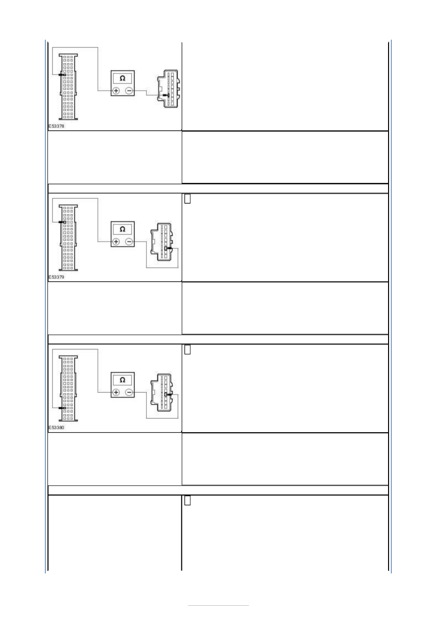
E20: CHECK CIRCUIT CMM19A (BN/YE) FOR OPEN

Measure the resistance between the PSE module 
C2MM01-B pin 41, circuit CMM19A (BN/YE), harness 

side and the handset holder C2MM17 pin 11, circuit 
CMM19A (BN/YE), harness side. 

Is the resistance less than 1 ohm? 
Yes 

GO to E21

.  

No 

REPAIR the circuit. TEST the system for normal 
operation. 

E21: CHECK CIRCUIT VMM20A (GN/BN) FOR OPEN

Measure the resistance between the PSE module 
C2MM01-B pin 51, circuit VMM20A (GN/BN), harness 

side and the handset holder C2MM17 pin 12, circuit 
VMM20A (GN/BN), harness side. 

Is the resistance less than 1 ohm? 
Yes 

GO to E22

.  

No 

REPAIR the circuit. TEST the system for normal 
operation. 

E22: CHECK CIRCUIT VMM09A (YE/GY) FOR OPEN

Measure the resistance between the PSE module 
C2MM01-B pin 37, circuit VMM09A (YE/GY), harness 

side and the handset holder C2MM17 pin 5, circuit 
VMM09A (YE/GY), harness side. 


Is the resistance less than 1 ohm? 
Yes 

GO to E23

.  

No 

REPAIR the circuit. TEST the system for normal 
operation. 

E23: CHECK CIRCUIT RMM09A (BU/GN) FOR OPEN

Measure the resistance between the PSE module 
C2MM01-B pin 38, circuit RMM09A (BU/GN), harness 

side and the handset holder C2MM17 pin 13, circuit 
RMM09A (BU/GN), harness side. 

Is the resistance less than 1 ohm? 
Yes 

GO to E24

.  

No 

REPAIR the circuit. TEST the system for normal 
operation. 

E24: CHECK CIRCUIT VMM12A (WH/BN) FOR OPEN

Measure the resistance between the PSE module 
C2MM01-B pin 39, circuit VMM12A (WH/BN), harness 

side and the handset holder C2MM17 pin 6, circuit 
VMM12A (WH/BN), harness side. 

Is the resistance less than 1 ohm? 
Yes 

GO to E13

.  

No 

REPAIR the circuit. TEST the system for normal 
operation. 

E25: CHECK CIRCUIT RMM12A (VT/BN) FOR OPEN

Measure the resistance between the PSE module 
C2MM01-B pin 40, circuit RMM12A (VT/BN), harness 

side and the handset holder C2MM17 pin 14, circuit 
RMM12A (VT/BN), harness side. 


Is the resistance less than 1 ohm? 
Yes 

INSTALL a new PSE module.  
REFER to: 

Portable Support Electronics (PSE) Module


(415-01 Information and Entertainment System, 
Removal and Installation). 
TEST the system for normal operation. 

No 

REPAIR the circuit. TEST the system for normal 
operation. If the concern persists, INSTALL a new 
handset holder.  
REFER to: 

Handset Holder - Vehicles Without: Voice 

Control

 (415-01 Information and Entertainment 

System, Removal and Installation). 
TEST the system for normal operation. 


Information and Entertainment System - 
General Information - Navigation 
System—Vehicles With: Travel Pilot EX

S-MAX/Galaxy 2006.5 (02/2006-)


Print


Diagnosis and Testing 

General Equipment 

Inspection and Verification 

NOTE: If a new navigation system display module is installed, allow the data from the 
navigation CD ROM to download (approximately 10 minutes) to the navigation system 
display module before inputting a destination into the navigation system display module. 
The vehicle must then be driven until the navigation system is fully calibrated. Route 
guidance will commence at approximately 30% of the calibration process and at 100% of 
calibration the route guidance will be accurate. 

1. 1. Verify the customer concern. 

2. 2. Visually inspect for obvious signs of mechanical or electrical damage. 

Visual Inspection Chart 

3. 3. If an obvious cause for an observed or reported concern is found, correct the cause 

(if possible) before proceeding to the next step. 

4. 4. If the cause is not visually evident, refer to the Self-Diagnostic Mode. 

Self-Diagnostic Mode 

NOTE: It is necessary to carry out part of the system diagnosis outside of the workshop. 
Make sure there that are no large buildings/obstructions or metal objects in the 
immediate vicinity. 
NOTE: Make sure the navigation CD ROM is installed in the navigation system display 
module before entering the Self-Diagnostic Mode. 
NOTE: The navigation system display module will stay activated for up to ten minutes 
after the unit has been switched OFF. 

Switch the navigation system display module ON. 

The navigation system constantly monitors it's inputs and outputs. If a concern is detected, 
a diagnostic trouble code (DTC) will be stored in the navigation system memory. 

Worldwide Diagnostic System (WDS) 

Mechanical

Electrical

Navigation system display module  
Navigation system antenna  
Navigation CD ROM 

Fuse(s)  
Wiring harness  
Electrical connector(s)  
Navigation system display module 


Content   ..  732  733  734  735   ..