Ford Galaxy / Ford S-MAX. Manual - part 698
 

  Index      Ford     Ford Galaxy / Ford S-MAX - service repair manual 2006 year


Search            


Content   ..  696  697  698  699   ..


Ford Galaxy / Ford S-MAX. Manual - part 698


INSTALL a new front seat heater switch. TEST the 
system for normal operation. 

No 

REPAIR circuit GD138AP (BK), circuit GD133AR (BK), 
circuit GD133CE (BK) or circuit GD133AW (BK) as 
necessary. TEST the system for normal operation. 

PINPOINT TEST D : THE FRONT AND REAR WINDOW DEFROST SWITCH 
ILLUMINATION IS INOPERATIVE 

TEST CONDITIONS

DETAILS/RESULTS/ACTIONS

D1: CHECK THE FRONT AND REAR WINDOW DEFROST SWITCH FOR VOLTAGE

Disconnect Rear Window Defrost Switch C2RD09. 

Ignition switch in position II. 

Make sure that the illumination dimmer switch is in 
the full illumination position. 

Place the headlamp switch in the ON position. 

Measure the voltage between the rear window 
defrost switch C2RD09 pin 5, circuit CLN17H (BN), 

harness side and ground. 

Is the voltage greater than 10 volts? 
Yes 

GO to D2

.  

No 

REPAIR the circuit CLN17T (BN) or circuit CLN17G 
(BN) as necessary. TEST the system for normal 
operation. 

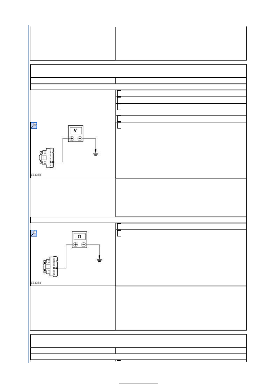
D2: CHECK CIRCUIT GD133BN (BK) FOR OPEN

Ignition switch in position 0. 

Measure the resistance between the rear window 
defrost switch C2RD09 pin 4, circuit GD133BN (BK), 

harness side and ground. 

Is the resistance less than 5 ohms? 
Yes 

INSTALL a new rear window defrost switch. TEST the 
system for normal operation. 

No 

REPAIR circuit GD133BN (BK), circuit GD133CH (BK) 
or circuit GD133AW (BK) as necessary. TEST the 
system for normal operation. 

PINPOINT TEST E : THE PARKING AID SWITCH ILLUMINATION IS 
INOPERATIVE 

TEST CONDITIONS

DETAILS/RESULTS/ACTIONS

E1: CHECK THE PARKING AID SWITCH FOR VOLTAGE


Disconnect Parking Aid Switch C2CA15. 

Ignition switch in position II. 

Make sure that the illumination dimmer switch is in 
the full illumination position. 

Place the headlamp switch in the ON position. 

Measure the voltage between the parking aid switch 
C2CA15 pin 5, circuit CLN17U (BN), harness side and 

ground. 

Is the voltage greater than 10 volts? 
Yes 

GO to E2

.  

No 

REPAIR the circuit CLN17U (BN) or circuit CLN17G 
(BN) as necessary. TEST the system for normal 
operation. 

E2: CHECK CIRCUIT GD133BR (BK) FOR OPEN

Ignition switch in position 0. 

Measure the resistance between the parking aid 
switch C2CA15 pin 4, circuit GD133BR (BK), harness 

side and ground. 

Is the resistance less than 5 ohms? 
Yes 

INSTALL a new parking aid switch. TEST the system 
for normal operation. 

No 

REPAIR circuit GD133BR (BK), circuit GD133CH (BK) 
or circuit GD133AW (BK) as necessary. TEST the 
system for normal operation. 

PINPOINT TEST F : THE ELECTRONIC PARKING BRAKE SWITCH 
ILLUMINATION IS INOPERATIVE 

TEST CONDITIONS

DETAILS/RESULTS/ACTIONS

F1: CHECK THE ELECTRONIC PARKING BRAKE SWITCH FOR VOLTAGE

Disconnect Electronic Parking Brake Switch C3CB09. 

Ignition switch in position II. 

Make sure that the illumination dimmer switch is in 
the full illumination position. 

Place the headlamp switch in the ON position. 

Measure the voltage between the electronic parking 
brake switch C3CB09 pin 1, circuit CLN17N (BN), 

harness side and ground. 


Is the voltage greater than 10 volts? 
Yes 

GO to F2

.  

No 

REPAIR circuit CLN17N (BN), circuit CLN17J (BN) or 
circuit CLN17G (BN) as necessary. TEST the system 
for normal operation. 

F2: CHECK THE ELECTRONIC PARKING BRAKE SWITCH FOR OPEN

Measure the resistance between the electronic 
parking brake switch C3CB09 pin 2, circuit GD138AL 

(BK), harness side and ground. 

Is the resistance less than 5 ohms? 
Yes 

INSTALL a new electronic parking brake switch. TEST 
the system for normal operation. 

No 

REPAIR circuit GD138AL (BK), circuit GD133AR (BK), 
circuit GD133CE (BK) or circuit GD133AW (BK) as 
necessary. TEST the system for normal operation. 


Instrument Cluster - Instrument Cluster

S-MAX/Galaxy 2006.5 (02/2006-)


Print


Description and Operation 

The instrument cluster is part of the central vehicle configuration and saves a copy of the 
configuration data stored in the GEM. It acts as a back-up copy in the event that the GEM 
must be renewed. 

After changing the instrument cluster, the current mileage of the vehicle must be entered 
using the Ford diagnostic unit. 

Is it possible to reset the mileage to zero on new vehicles. The following conditions apply: 

the 20 kilometer (mile) limit must not be exceeded,  
under 20 kilometers (miles), the mileage can be reset to zero a maximum of three times. 
However, resetting is only possible up to a total of 50 kilometers. 

For this purpose, the confirmation button on the steering wheel must be pressed for longer 
than 7 seconds. 

The instrument cluster can be diagnosed using IDS. 

Vehicles with low series instrument cluster 


Description 

Glow plug indicator 

Speed control indicator 

Gear change indicator (gear change recommendation) 

Air bag warning indicator 

Left-hand turn signal indicator 

Coolant temperature gauge 

Information and message center display / alarm system enabled 
(when ignition off) 

Fuel Level Gauge 

Right-hand turn signal indicator 

Item

1

2

3

4

5

6

7

8

9


Part Number

-

-

-

-

-

-

-

-

-

-


Content   ..  696  697  698  699   ..