Ford Galaxy / Ford S-MAX. Manual - part 651
 

  Index      Ford     Ford Galaxy / Ford S-MAX - service repair manual 2006 year


Search            


Content   ..  649  650  651  652   ..


Ford Galaxy / Ford S-MAX. Manual - part 651


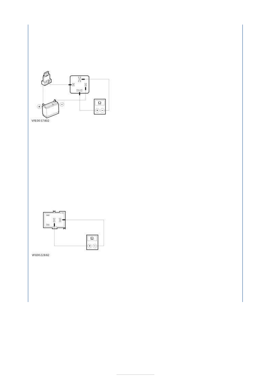
1. 1. Check the normally open contact in the unswitched state: 

1. Measure the resistance at blower relay H402, between pin 37 and pin 36, 

component side. 

2. Is a resistance of more than 10,000 Ohms measured? 
3. If yes, go to 4. 
4. If no, RENEW blower relay H402. 

2. 2. Check the normally open contact in the switched state: 

1. Using a fused test cable (1 A), connect pin 39 of blower relay H402, component 

side, to the battery positive terminal. 

2. Use a test cable to connect pin 38 of blower relay H402, component side, to the 

battery negative terminal. 

3. Measure the resistance at blower relay H402, between pin 37 and pin 36, 

component side. 

4. Is a resistance of less than 2 Ohms registered? 
5. If yes, then blower relay H402 is OK. 
6. If no, RENEW blower relay H402. 

A/C clutch relay H401 

1. 1. Check the normally open contact in the unswitched state: 

1. Measure the resistance at A/C clutch relay H401, between pin 28 and pin 29, 

component side. 

2. Is a resistance of more than 10,000 Ohms measured? 
3. If yes, go to 4. 
4. If no, RENEW A/C clutch relay H401. 


2. 2. Check the normally open contact in the switched state: 

1. Use a fused test cable (1 A) to connect pin 31 of A/C clutch relay H401, component 

side, to the battery positive terminal. 

2. Use a test cable to connect pin 30 of A/C clutch relay H401, component side, to the 

battery negative terminal. 

3. Measure the resistance at A/C clutch relay H401, between pin 28 and pin 29, 

component side. 

4. Is a resistance of less than 2 Ohms registered? 
5. If yes, then A/C clutch relay H401 is OK. 
6. If no, RENEW A/C clutch relay H401. 


Climate Control System - General 
Information - Auxiliary Climate Control

S-MAX/Galaxy 2006.5 (02/2006-)


Print


Diagnosis and Testing 

Refer to Wiring Diagrams Section 412-03A, for schematic and connector 
information.  

Special Tool(s) 

General Equipment 

Inspection and Testing 

1. 1. VERIFY the customer concern. 

2. 2. Visually CHECK for any obvious mechanical or electrical damage. 

NOTE: Ensure correct locking of wiring harness connectors. 

Visual Inspection 

3. 3. RECTIFY any obvious causes for a concern found during the visual inspection 

before performing any further tests. CHECK the operation of the system. 

4. 4. If the concern is still present after the visual inspection, perform fault diagnosis on 

the electronic engine management, the charging system, the generic electronic 
module (GEM), the instrument cluster, the electronic automatic temperature control 
(EATC) and the auxiliary climate control module using WDS and RECTIFY the fault
(s) displayed in accordance with the fault description. CHECK the operation of the 
system. 

5. 5. On a vehicle without stored fault(s), continue according to the Symptom Chart and 

the corresponding symptom. 

6. 6. Following checking or elimination of the fault(s) and after completion of operations, 

the fault memories of all vehicle modules must be READ OUT and any stored faults 
must be DELETED. READ OUT all fault memories again following a road test. 

Trouble code table - vehicles with auxiliary climate control 

Trouble code table - auxiliary climate control 

Terminal Probe Kit 

418-S035 

Digital Multimeter (compatible with K-type 
thermocouple)
Worldwide Diagnostic System (WDS)
Refrigerant center
Thermometer - Fluke 80 PK-8 (FSE number 260 
4102 001 07)

Mechanical

Electrical

Refrigerant lines  

Condenser  

Drive belt  

A/C compressor 

Fuses  

Wiring harness  

Connector 


Symptom chart 

Symptom chart 

Diagnostic 

trouble code.

Description

Action

B10BA11

Auxiliary climate control blower control 
module, short-circuited (short to ground)

GO to Pinpoint Test 

A. 

B10BA12

Auxiliary climate control blower control 
module, short circuit to voltage

GO to Pinpoint Test 

A. 

B10BA13

Auxiliary climate control blower control 
module, open circuit

GO to Pinpoint Test 

A. 

B10B012

Auxiliary climate control blower relay circuit, 
short circuit to voltage

GO to Pinpoint Test 

A. 

B10B014

Auxiliary climate control blower relay circuit, 
open circuit or short-circuited (short to 
ground)

GO to Pinpoint Test 

A. 

B10B711

Auxiliary climate control air outlet 
temperature sensor circuit, short-circuited 
(short to ground)

GO to Pinpoint Test 

D. 

B10B715

Auxiliary climate control air outlet 
temperature sensor circuit, open circuit or 
short to voltage

GO to Pinpoint Test 

D. 

B102D12

Auxiliary climate control temperature control 
flap actuator circuit, short circuit to voltage

GO to Pinpoint Test 

C. 

B102D14

Auxiliary climate control temperature control 
flap actuator circuit, open circuit or short-
circuited (short to ground)

GO to Pinpoint Test 

C. 

B1B7A12

Auxiliary climate control expansion/cut-out 
valve circuit, short circuit to voltage

GO to Pinpoint Test 

B. 

B1B7A14

Auxiliary climate control expansion/cut-out 
valve circuit, open circuit or short-circuited 
(short to ground)

GO to Pinpoint Test 

B. 

B1B8111

Auxiliary climate control evaporator 
temperature sensor circuit, short-circuited 
(short to ground)

GO to Pinpoint Test 

B. 

B1B8115

Auxiliary climate control evaporator 
temperatures sensor circuit, open circuit or 
short to voltage

GO to Pinpoint Test 

B. 

P9B6916

Power supply voltage below limit

GO to Pinpoint Test 

B. 

P9B6917

Power supply voltage above limit

GO to Pinpoint Test 

B. 

U014000

No communication possible with the generic 
electronic module (GEM)

REFER to: Kommunikations-
Netzwerk (418-00, Diagnosis and 
Testing).

U001000

No communications possible via the MS CAN 
bus.

REFER to: Kommunikations-
Netzwerk (418-00, Diagnosis and 
Testing).

Symptom

Possible Sources

Action

Auxiliary climate control blower motor 
inoperative/not operating correctly

Fuse(s) 
Circuit(s) 
Auxiliary climate control blower 

relay 

Auxiliary climate control blower 

motor 

Blower switch 
Auxiliary climate control blower 

control module 

Auxiliary climate control module 
CJB (Central Junction Box) 

*
*
*

*

*
*

*
*

GO to 

Pinpoint Test 

A. 


*


Content   ..  649  650  651  652   ..