Ford Galaxy / Ford S-MAX. Manual - part 650
 

  Index      Ford     Ford Galaxy / Ford S-MAX - service repair manual 2006 year


Search            


Content   ..  648  649  650  651   ..


Ford Galaxy / Ford S-MAX. Manual - part 650


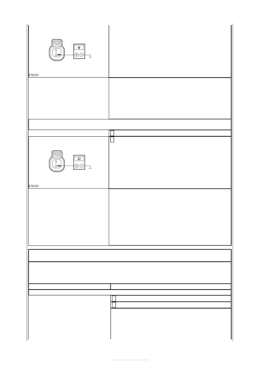
Is a voltage measured? 
Yes 

LOCATE and RECTIFY the short to voltage in circuit 
CBP01A (BU/GN) between the GEM and the electric 
booster heater using the Wiring Diagrams. CHECK 
the operation of the system. 

No 

GO to P13

.  

P13: CHECK THE CIRCUIT BETWEEN THE ELECTRIC BOOSTER HEATER AND THE GEM 
FOR A SHORT TO GROUND

Ignition switch in position 0. 

Measure the resistance between the electric booster 
heater, connector C2HP03, pin 2, circuit CBP01A 

(BU/GN), wiring harness side and ground. 

Is a resistance of more than 10,000 Ohms measured? 
Yes 

RENEW the electric booster heater. CHECK the 
operation of the system. If the system is still 
inoperative, CHECK the GEM and RENEW if 
necessary. CHECK the operation of the system. 

No 

LOCATE and RECTIFY the short to ground in circuit 
CBP01A (BU/GN) between the GEM and the electric 
booster heater using the Wiring Diagrams. CHECK 
the operation of the system. 

PINPOINT TEST Q : PROGRAMMABLE FUEL-FIRED BOOSTER HEATER 
INOPERATIVE 

NOTE: The fuel fired booster heater is equipped with an integrated undervoltage 
protection. This switches off the fuel-fired booster heater when the supply voltage falls 
below 10 V for longer than 20 seconds. Before performing further checks, ensure that 
the vehicle battery is OK and that the charge state is sufficient. 

TEST CONDITIONS

DETAILS/RESULTS/ACTIONS

Q1: CHECK FUSE F277

Ignition switch in position 0. 

CHECK F27 (EJB). 

Is the fuse OK? 
Yes 

GO to Q2

.  

No 

RENEW fuse F27 (30 A). CHECK the operation of the 


system. If the fuse blows again, LOCATE and 
REPAIR the short using the Wiring Diagrams. 

Q2: CHECK THE VOLTAGE AT FUSE F27

Connect Fuse F27 (EJB). 

Measure the voltage between fuse F27 (30 A) and 
ground. 

Does the meter display battery voltage? 
Yes 

GO to Q3

.  

No 

REPAIR the voltage supply to fuse F27. CHECK the 
operation of the system. 

Q3: CHECK THE VOLTAGE AT THE PROGRAMMABLE FUEL-FIRED BOOSTER HEATER

Disconnect Connector C1HF01-C from the 
programmable fuel-fired booster heater. 

Measure the voltage between the programmable 
fuel-fired booster heater, connector C1HF01-C, pin 

3, circuit SBB27A (BU/RD), wiring harness side and 
ground. 

Does the meter display battery voltage? 
Yes 

GO to Q5

.  

No 

GO to Q4

.  

Q4: CHECK FOR OPEN CIRCUIT BETWEEN THE PROGRAMMABLE FUEL-FIRED 
BOOSTER HEATER AND THE EJB

Disconnect Connector C1BB01-A from the EJB. 

Measure the resistance between the programmable 
fuel-fired booster heater, connector C1HF01-C, pin 

3, circuit SBB27A (BU/RD), wiring harness side and 
the EJB, connector C1BB01-A, circuit SBB32A 
(BU/RD), wiring harness side. 

Is a resistance of less than 2 Ohms measured? 
Yes 

CHECK the EJB and RENEW it if necessary. CHECK 
the operation of the system. 

No 

LOCATE and REPAIR the break in circuit SBB27A 
(VT/RD) between the programmable fuel-fired 
booster heater and the EJB with the aid of the 
Wiring Diagrams. CHECK the operation of the 
system. 

Q5: CHECK THE GROUND CONNECTION OF THE PROGRAMMABLE FUEL-FIRED 
BOOSTER HEATER

Measure the resistance between the programmable 
fuel-fired booster heater, connector C1HF01-C, pin 

4, circuit GD132L (BK/VT), wiring harness side and 
ground. 


Is a resistance of less than 2 Ohms measured? 
Yes 

CHECK and if necessary RENEW the programmable 
fuel-fired booster heater. CHECK the operation of 
the system. 

No 

LOCATE and REPAIR the open circuit between the 
programmable fuel-fired booster heater and ground 
connection G1D132-A with the aid of the Wiring 
Diagrams. CHECK the operation of the system. 

PINPOINT TEST R : FUEL-FIRED BOOSTER HEATER (COOLANT PUMP) 
INOPERATIVE - VEHICLES WITH PROGRAMMABLE FUEL-FIRED BOOSTER 
HEATER 

TEST 

CONDITIONS

DETAILS/RESULTS/ACTIONS

R1: CHECK THE CIRCUIT BETWEEN THE FUEL-FIRED BOOSTER HEATER (COOLANT 
PUMP) AND THE PROGRAMMABLE FUEL-FIRED BOOSTER HEATER FOR OPEN CIRCUIT

Ignition switch in position 0. 

Disconnect Connector C1HF02 from the fuel-fired booster heater (coolant 
pump). 

Disconnect Connector C1HF01-C from the programmable fuel-fired booster 
heater. 

Measure the resistance between the programmable fuel-fired booster 
heater, connector C1HF01-C, pin 9, circuit RHF03A (WH/VT), wiring 

harness side and the fuel-fired booster heater (coolant pump), connector 
C1HF02, pin 2, circuit RHF03A (WH/VT), wiring harness side. 

Is a resistance of less than 2 Ohms registered? 
Yes 

GO to R2

.  

No 

LOCATE and REPAIR the break in circuit RHF03A (WH/VT) between the 
programmable fuel-fired booster heater and the fuel-fired booster heater 
(coolant pump) with the aid of the Wiring Diagrams. CHECK the operation 
of the system. 

R2: CHECK THE CIRCUIT BETWEEN THE FUEL-FIRED BOOSTER HEATER (COOLANT 
PUMP) AND THE PROGRAMMABLE FUEL-FIRED BOOSTER HEATER FOR OPEN CIRCUIT

Measure the resistance between the programmable fuel-fired booster 
heater, connector C1HF01-C, pin 10, circuit CHF03A (GN/OG), wiring 

harness side and the fuel-fired booster heater (coolant pump), connector 
C1HF02, pin 1, circuit CHF03A (GN/OG), wiring harness side. 

Is a resistance of less than 2 Ohms registered? 
Yes 

RENEW the fuel-fired booster heater (coolant pump). CHECK the operation 
of the system. 

No 

LOCATE and REPAIR the break in circuit CHF03A (GN/OG) between the 
programmable fuel-fired booster heater and the fuel-fired booster heater 
(coolant pump) with the aid of the Wiring Diagrams. CHECK the operation 


Component Tests 

Blower relay H402 

of the system. 

PINPOINT TEST S : BOOSTER HEATER FUEL PUMP INOPERATIVE 

TEST CONDITIONS

DETAILS/RESULTS/ACTIONS

S1: CHECK FOR OPEN CIRCUIT BETWEEN THE BOOSTER HEATER FUEL PUMP AND THE 
FUEL-FIRED BOOSTER HEATER 

Ignition switch in position 0. 

Disconnect Connector C3HF02 from the booster 
heater fuel pump. 

Disconnect Connector C1HF01-C from the fuel-fired 
booster heater. 

Measure the resistance between the programmable 
fuel-fired booster heater, connector C1HF01-C, pin 

7, circuit CHF01A (BN/BU), wiring harness side and 
the booster heater fuel pump, connector C3HF02, pin 
1, circuit CHF01C (BN/BU), wiring harness side. 

Is a resistance of less than 2 Ohms registered? 
Yes 

GO to S2

.  

No 

LOCATE and REPAIR the open circuit between the 
programmable fuel-fired booster heater and the 
booster heater fuel pump with the aid of the Wiring 
Diagrams. CHECK the operation of the system. 

S2: CHECK THE GROUND CONNECTION OF THE BOOSTER HEATER FUEL PUMP

Measure the resistance between the booster heater 
fuel pump, connector C3HF02, pin 2, circuit GD152F 

(BK/BU), wiring harness side. 

Is a resistance of less than 2 Ohms registered? 
Yes 

RENEW the booster heater fuel pump. CHECK the 
operation of the system. 

No 

LOCATE and RECTIFY the break in the circuit 
between ground connection G4D151 and the booster 
heater fuel pump with the aid of the Wiring 
Diagrams. CHECK the operation of the system. 


Content   ..  648  649  650  651   ..