Ford Galaxy / Ford S-MAX. Manual - part 649
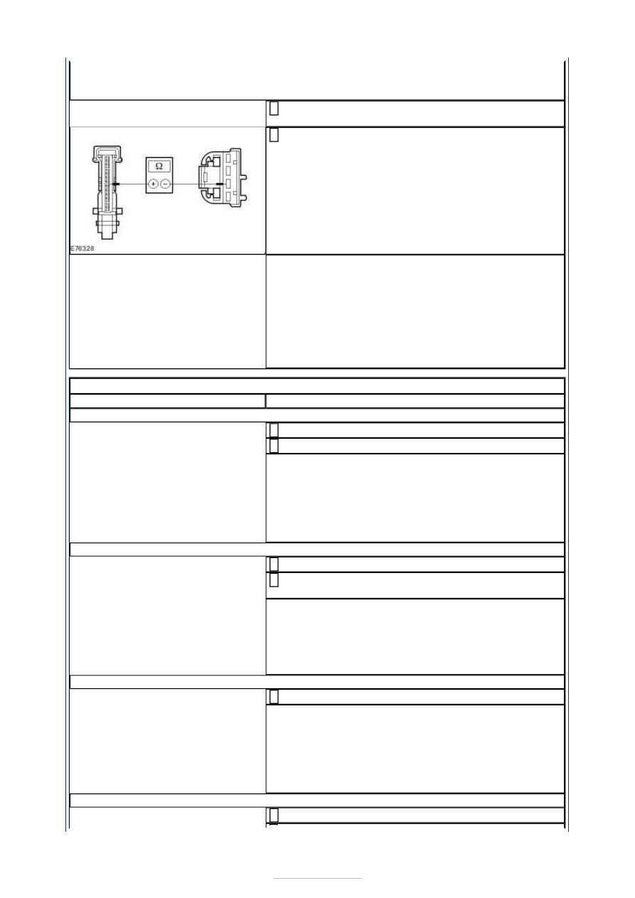
O4: CHECK THE CIRCUIT BETWEEN THE INTERIOR TEMPERATURE SENSOR AND THE
ELECTRONIC AUTOMATIC TEMPERATURE CONTROL (EATC) MODULE FOR OPEN
CIRCUIT
Disconnect Connector C2H101-B from the EATC
module.
1
Measure the resistance between the interior
temperature sensor, connector C2H415, pin 3,
circuit RH104FA (BU/GN), wiring harness side and
the EATC module, connector C2H101-B, Pin 20,
circuit RH104FA (BU/GN), wiring harness side.
2
Is a resistance of less than 2 Ohms registered?
Yes
CHECK the EATC module, if necessary INSTALL a
new one. CHECK the operation of the system.
No
LOCATE and REPAIR the break in the circuit between
the passenger compartment temperature sensor and
the EATC module using the Wiring Diagrams. CHECK
the operation of the system.
PINPOINT TEST P : ELECTRIC BOOSTER HEATER INOPERATIVE
TEST CONDITIONS
DETAILS/RESULTS/ACTIONS
P1: CHECK FUSE F16
Ignition switch in position 0.
1
CHECK F16 (EJB).
2
Is the fuse OK?
Yes
GO to P2
.
No
RENEW fuse F16 (80 A). CHECK the operation of the
system. If the fuse blows again, LOCATE and REPAIR
the short using the Wiring Diagrams.
P2: CHECK THE VOLTAGE AT FUSE F16
Connect F16 (EJB).
1
Measure the voltage between fuse F16 (80 A) and
ground.
2
Does the meter display battery voltage?
Yes
GO to P3
.
No
REPAIR the voltage supply to fuse F16. CHECK the
operation of the system.
P3: CHECK FUSE F4
CHECK F4 (CJB).
1
Is the fuse OK?
Yes
GO to P4
.
No
RENEW fuse F4 (7.5 A). CHECK the operation of the
system. If the fuse blows again, LOCATE and REPAIR
the short using the Wiring Diagrams.
P4: CHECK THE VOLTAGE AT FUSE F4
Connect F4 (CJB).
1