Ford Galaxy / Ford S-MAX. Manual - part 647
 

  Index      Ford     Ford Galaxy / Ford S-MAX - service repair manual 2006 year


Search            


Content   ..  645  646  647  648   ..


Ford Galaxy / Ford S-MAX. Manual - part 647


Wiring Diagrams. CHECK the operation of the 
system. 

PINPOINT TEST L : FAULT IN LEFT-HAND CENTRE VENTS AIR OUTLET 
TEMPERATURE SENSOR CIRCUIT - VEHICLES WITH ELECTRONIC 
AUTOMATIC TEMPERATURE CONTROL (EATC) 

TEST CONDITIONS

DETAILS/RESULTS/ACTIONS

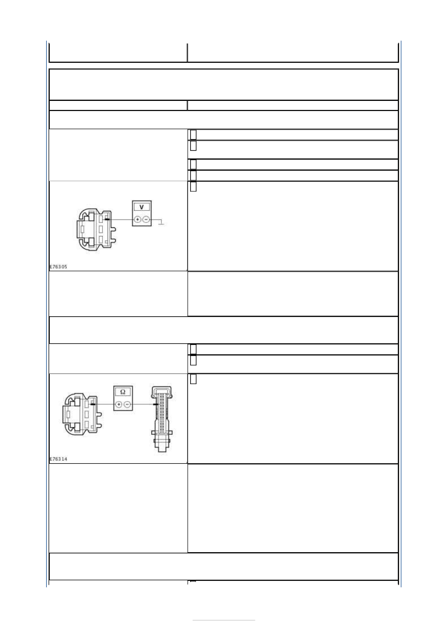
L1: CHECK VOLTAGE AT LEFT-HAND CENTER VENTS AIR OUTLET TEMPERATURE 
SENSOR

Ignition switch in position 0. 

Disconnect Connector C2H414-A from left-hand 
centre vents air outlet temperature sensor. 

Ignition switch in position II. 

Switch on the air conditioning (A/C). 

Measure the voltage between the left-hand centre 
vents air outlet temperature sensor, connector 

C2H414-A, pin 1, circuit VH409A (WH), wiring 
harness side and ground. 

Is a voltage of approx. 5 volts measured? 
Yes 

GO to L3

.  

No 

GO to L2

.  

L2: CHECK THE CIRCUIT BETWEEN THE LEFT-HAND CENTER VENTS AIR OUTLET 
TEMPERATURE SENSOR AND THE ELECTRONIC AUTOMATIC TEMPERATURE CONTROL 
(EATC) MODULE FOR OPEN CIRCUIT

Ignition switch in position 0. 

Disconnect Connector C2H101-B from the EATC 
module. 

Measure the resistance between the left-hand centre 
vents air outlet temperature sensor, connector 

C2H414-A, pin 1, circuit VH409A (WH),wiring 
harness side and the EATC module, connector 
C2H101-B, pin 10, circuit VH409A (WH), wiring 
harness side. 

Is a resistance of less than 2 Ohms registered? 
Yes 

CHECK the EATC module, if necessary INSTALL a 
new one. CHECK the operation of the system. 

No 

LOCATE and REPAIR the break in circuit VH409A 
(WH) between the left-hand centre vents air outlet 
temperature sensor and the EATC module using the 
Wiring Diagrams. CHECK the operation of the 
system. 

L3: CHECK THE CIRCUIT BETWEEN THE LEFT-HAND CENTER VENTS AIR OUTLET 
TEMPERATURE SENSOR AND THE ELECTRONIC AUTOMATIC TEMPERATURE CONTROL 
(EATC) MODULE FOR OPEN CIRCUIT


Ignition switch in position 0. 

Disconnect Connector C2H101-B from the EATC 
module. 

Measure the resistance between the left-hand centre 
vents air outlet temperature sensor, connector 

C2H414-A, pin 3, circuit RH105R (GN), wiring 
harness side and the EATC module, connector 
C2H101-B, pin 17, circuit RH105T (GN), wiring 
harness side. 

Is a resistance of less than 2 Ohms registered? 
Yes 

GO to L4

.  

No 

LOCATE and REPAIR the break in the circuit between 
the left-hand center vents air outlet temperature 
sensor and the EATC module using the Wiring 
Diagrams. CHECK the operation of the system. 

L4: CHECK FOR SHORT CIRCUIT BETWEEN THE LEFT-HAND CENTER VENTS AIR 
OUTLET TEMPERATURE SENSOR AND THE EATC MODULE

Measure the resistance between the EATC module, 
connector C2H101-B, pin 10, circuit VH409A (WH), 

wiring harness side and the EATC module, connector 
C2H101-B, pin 17, circuit RH105T (GN), wiring 
harness side. 

Is a resistance of more than 10,000 Ohms measured? 
Yes 

GO to L5

.  

No 

LOCATE and REPAIR the short in the circuits between 
the left-hand centre vents air outlet temperature 
sensor and the EATC module using the Wiring 
Diagrams. CHECK the operation of the system. 

L5: CHECK FOR SHORT CIRCUIT TO GROUND BETWEEN THE LEFT-HAND CENTER 
VENTS AIR OUTLET TEMPERATURE SENSOR AND THE EATC MODULE

Measure the resistance between the EATC module, 
connector C2H101-B, pin 10, circuit VH409A (WH), 

wiring harness side and ground. 

Is a resistance of more than 10,000 Ohms measured? 
Yes 

RENEW the left-hand centre vents air outlet 
temperature sensor. CHECK the operation of the 
system. 

No 


LOCATE and REPAIR the short to ground in the 
circuits between the left-hand center vents air outlet 
temperature sensor and the EATC module using the 
Wiring Diagrams. CHECK the operation of the 
system. 

PINPOINT TEST M : FAULT IN LEFT-HAND FOOTWELL AIR OUTLET 
TEMPERATURE SENSOR CIRCUIT - VEHICLES WITH ELECTRONIC 
AUTOMATIC TEMPERATURE CONTROL (EATC) 

TEST CONDITIONS

DETAILS/RESULTS/ACTIONS

M1: CHECK VOLTAGE AT LEFT-HAND FOOTWELL AIR OUTLET TEMPERATURE SENSOR

Ignition switch in position 0. 

Disconnect Connector C2H414-C from left-hand 
footwell air outlet temperature sensor. 

Ignition switch in position II. 

Switch on the air conditioning (A/C). 

Measure the voltage between the left-hand footwell 
air outlet temperature sensor, connector C2H414-C, 

pin 1, circuit VH410A (GY/BU), wiring harness side 
and ground. 

Is a voltage of approx. 5 volts measured? 
Yes 

GO to M3

.  

No 

GO to M2

.  

M2: CHECK THE CIRCUIT BETWEEN THE LEFT-HAND FOOTWELL AIR OUTLET 
TEMPERATURE SENSOR AND THE ELECTRONIC AUTOMATIC TEMPERATURE CONTROL 
(EATC) MODULE FOR OPEN CIRCUIT

Ignition switch in position 0. 

Disconnect Connector C2H101-B from the EATC 
module. 

Measure the resistance between the left-hand 
footwell air outlet temperature sensor, connector 

C2H414-C, pin 1, circuit VH410A (GY/BU), wiring 
harness side and the EATC module, connector 
C2H101-B, Pin 9, circuit VH410A (GY/BU), wiring 
harness side. 

Is a resistance of less than 2 Ohms registered? 
Yes 

CHECK the EATC module, if necessary INSTALL a 
new one. CHECK the operation of the system. 

No 

LOCATE and REPAIR the break in circuit VH410A 
(GY/BU) between the left-hand footwell air outlet 
temperature sensor and the EATC module using the 
Wiring Diagrams. CHECK the operation of the 
system. 

M3: CHECK THE CIRCUIT BETWEEN THE LEFT-HAND FOOTWELL AIR OUTLET 


TEMPERATURE SENSOR AND THE ELECTRONIC AUTOMATIC TEMPERATURE CONTROL 
(EATC) MODULE FOR OPEN CIRCUIT

Ignition switch in position 0. 

Disconnect Connector C2H101-B from the EATC 
module. 

Measure the resistance between the left-hand 
footwell air outlet temperature sensor, connector 

C2H414-C, pin 3, circuit RH105S (GN), wiring 
harness side and the EATC module, connector 
C2H101-B, pin 17, circuit RH105T (GN), wiring 
harness side. 

Is a resistance of less than 2 Ohms registered? 
Yes 

GO to M4

.  

No 

LOCATE and REPAIR the break in the circuit between 
the left-hand footwell air outlet temperature sensor 
and the EATC module using the Wiring Diagrams. 
CHECK the operation of the system. 

M4: CHECK FOR SHORT CIRCUIT BETWEEN THE LEFT-HAND FOOTWELL AIR OUTLET 
TEMPERATURE SENSOR AND THE EATC MODULE

Measure the resistance between the EATC module, 
connector C2H101-B, pin 9, circuit VH410A (GY/BU), 

wiring harness side and the EATC module, connector 
C2H101-B, pin 17, circuit RH105T (GN), wiring 
harness side. 

Is a resistance of more than 10,000 Ohms measured? 
Yes 

GO to M5

.  

No 

LOCATE and REPAIR the short in the circuits between 
the left-hand footwell air outlet temperature sensor 
and the EATC module using the Wiring Diagrams. 
CHECK the operation of the system. 

M5: CHECK FOR SHORT CIRCUIT TO GROUND BETWEEN THE LEFT-HAND FOOTWELL 
AIR OUTLET TEMPERATURE SENSOR AND THE EATC MODULE

Measure the resistance between the EATC module, 
connector C2H101-B, pin 9, circuit VH410A (GY/BU), 

wiring harness side and ground. 

Is a resistance of more than 10,000 Ohms measured? 
Yes 

RENEW the left-hand footwell air outlet temperature 
sensor. CHECK the operation of the system. 


Content   ..  645  646  647  648   ..