Ford Galaxy / Ford S-MAX. Manual - part 645
 

  Index      Ford     Ford Galaxy / Ford S-MAX - service repair manual 2006 year


Search            


Content   ..  643  644  645  646   ..


Ford Galaxy / Ford S-MAX. Manual - part 645


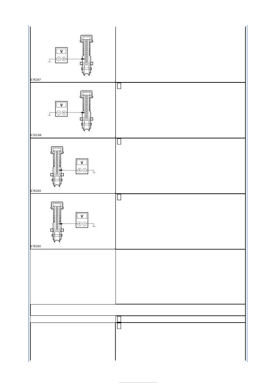
Measure the voltage between the EATC module, 
connector C2H101-A, pin 4, circuit CH239A 

(BU/WH), wiring harness side and ground. 

Measure the voltage between the EATC module, 
connector C2H101-A, pin 16, circuit CH240A 

(GN/WH), wiring harness side and ground. 

Measure the voltage between the EATC module, 
connector C2H101-A, pin 17, circuit CH241A 

(GY/BN), wiring harness side and ground. 

Is a voltage measured during one or more 
measurements? 
Yes 

LOCATE and REPAIR the short to voltage in the 
relevant circuit(s) between the left-hand temperature 
control flap actuator and the EATC module using the 
Wiring Diagrams. CHECK the operation of the 
system. 

No 

GO to I5

.  

I5: CHECK THE CIRCUITS BETWEEN THE LEFT-HAND TEMPERATURE CONTROL FLAP 
ACTUATOR AND THE EATC MODULE FOR SHORT TO GROUND

Ignition switch in position 0. 

Measure the resistance between the EATC module, 
connector C2H101-A, pin 3, circuit CH238A (YE/OG), 

wiring harness side and ground. 


Measure the resistance between the EATC module, 
connector C2H101-A, pin 4, circuit CH239A 

(BU/WH), wiring harness side and ground. 

Measure the resistance between the EATC module, 
connector C2H101-A, pin 16, circuit CH240A 

(GN/WH), wiring harness side and ground. 

Measure the resistance between the EATC module, 
connector C2H101-A, pin 17, circuit CH241A 

(GY/BN), wiring harness side and ground. 

Is a resistance of more than 10,000 Ohms measured in 
all of the measurements? 
Yes 

GO to I6

.  

No 

LOCATE and REPAIR the short to ground in the 
relevant circuit(s) between the left-hand temperature 
control flap actuator and the EATC module using the 
Wiring Diagrams. CHECK the operation of the 
system. 

I6: CHECK THE CIRCUITS BETWEEN THE LEFT-HAND TEMPERATURE CONTROL FLAP 
ACTUATOR AND THE EATC MODULE FOR SHORT CIRCUIT

Measure the resistance between the EATC module, 
connector C2H101-A, pin 3, circuit CH238A (YE/OG), 

wiring harness side and the EATC module, connector 
C2H101-A, pin 12, circuit CH237A (VT/GY), wiring 
harness side. 


Measure the resistance between the EATC module, 
connector C2H101-A, pin 3, circuit CH238A (YE/OG), 

wiring harness side and the EATC module, connector 
C2H101-A, pin 4, circuit CH239A (BU/WH), wiring 
harness side. 

Measure the resistance between the EATC module, 
connector C2H101-A, pin 3, circuit CH238A (YE/OG), 

wiring harness side and the EATC module, connector 
C2H101-A, pin 16, circuit CH240A (GN/WH), wiring 
harness side. 

Measure the resistance between the EATC module, 
connector C2H101-A, pin 3, circuit CH238A (YE/OG), 

wiring harness side and the EATC module, connector 
C2H101-A, pin 17, circuit CH241A (GY/BN), wiring 
harness side. 

Measure the resistance between the EATC module, 
connector C2H101-A, pin 12, circuit CH237A 

(VT/GY), wiring harness side and the EATC module, 
connector C2H101-A, pin 4, circuit CH239A (BU/WH), 
wiring harness side. 

Measure the resistance between the EATC module, 
connector C2H101-A, pin 12, circuit CH237A 

(VT/GY), wiring harness side and the EATC module, 
connector C2H101-A, pin 16, circuit CH240A 
(GN/WH), wiring harness side. 


Measure the resistance between the EATC module, 
connector C2H101-A, pin 12, circuit CH237A 

(VT/GY), wiring harness side and the EATC module, 
connector C2H101-A, pin 17, circuit CH241A 
(GY/BN), wiring harness side. 

Measure the resistance between the EATC module, 
connector C2H101-A, pin 4, circuit CH239A 

(BU/WH), wiring harness side and the EATC module, 
connector C2H101-A, pin 16, circuit CH240A 
(GN/WH), wiring harness side. 

Measure the resistance between the EATC module, 
connector C2H101-A, pin 4, circuit CH239A 

(BU/WH), wiring harness side and the EATC module, 
connector C2H101-A, pin 17, circuit CH241A 
(GY/BN), wiring harness side. 

Measure the resistance between the EATC module, 
connector C2H101-A, pin 16, circuit CH240A 

(GN/WH), wiring harness side and the EATC module, 
connector C2H101-A, pin 17, circuit CH241A 
(GY/BN), wiring harness side. 

10 

Is a resistance of more than 10,000 Ohms measured in 
all of the measurements? 
Yes 

RENEW the left-hand temperature control flap 
actuator CHECK the operation of the system. 

No 

LOCATE and REPAIR the short between the relevant 
circuits between the left-hand temperature control 
flap actuator and the EATC module using the Wiring 
Diagrams. CHECK the operation of the system. 


Content   ..  643  644  645  646   ..