Ford Galaxy / Ford S-MAX. Manual - part 637
 

  Index      Ford     Ford Galaxy / Ford S-MAX - service repair manual 2006 year


Search            


Content   ..  635  636  637  638   ..


Ford Galaxy / Ford S-MAX. Manual - part 637


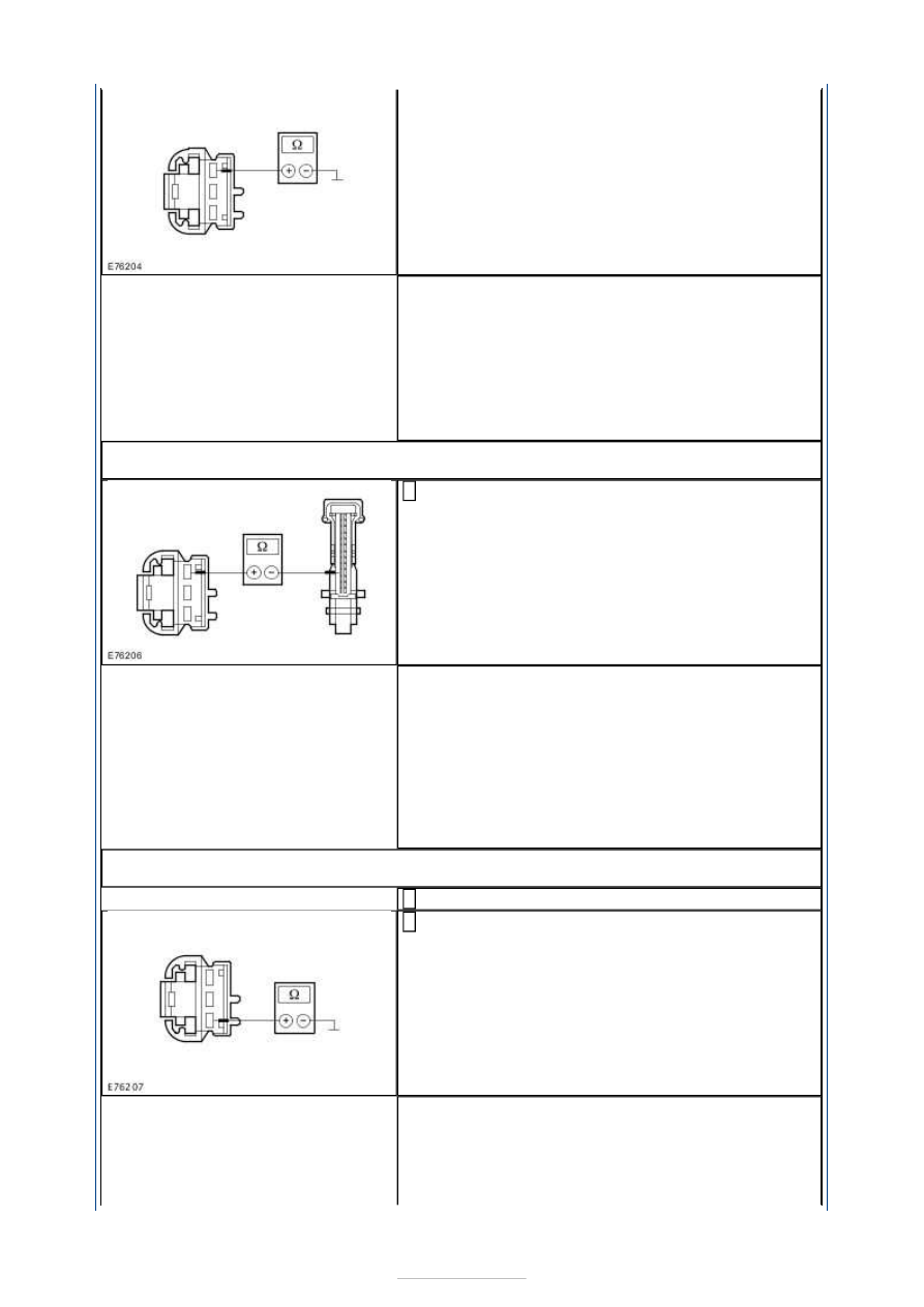
Is a resistance of more than 10,000 Ohms measured? 
Yes 

GO to E17

.  

No 

LOCATE and REPAIR the short to ground in circuit 
VH406A (VT/BN) between the EATC module and the 
evaporator temperature sensor with the aid of the 
Wiring Diagrams. CHECK the operation of the 
system. 

E17: CHECK FOR OPEN CIRCUIT BETWEEN THE EVAPORATOR TEMPERATURE SENSOR 
AND THE EATC MODULE

Measure the resistance between the evaporator 
temperature sensor, connector C2H406-A, pin 1, 

circuit VH406A (VT/BN), wiring harness side and 
the EATC module, connector C2H101-B, pin 4, 
circuit VH406A (VT/BN), wiring harness side. 

Is a resistance of less than 2 Ohms registered? 
Yes 

CHECK the EATC module, if necessary INSTALL a 
new one. CHECK the operation of the system. 

No 

LOCATE and REPAIR the break in circuit VH406A 
(VT/BN) between the evaporator temperature 
sensor and the EATC module with the aid of the 
Wiring Diagrams. CHECK the operation of the 
system. 

E18: CHECK THE GROUND CONNECTION OF THE EVAPORATOR TEMPERATURE 
SENSOR

Ignition switch in position 0. 

Measure the resistance between the evaporator 
temperature sensor, connector C2H406-A, pin 3, 

circuit RH105P (all except vehicles with electronic 
automatic temperature control (EATC): circuit 
RH105U) (GN), wiring harness side and ground. 

Is a resistance of less than 2 Ohms registered? 
Yes 

RENEW the evaporator temperature sensor. CHECK 
the operation of the system. 

No 


- All except vehicles with electronic automatic 
temperature control (EATC):

GO to E19

.  

- Vehicles with electronic automatic temperature 
control (EATC)

GO to E20

.  

E19: CHECK THE CIRCUIT BETWEEN THE EVAPORATOR TEMPERATURE SENSOR AND 
THE GEM FOR OPEN CIRCUIT

Disconnect Connector C1BP02-C from the GEM. 

Measure the resistance between the evaporator 
temperature sensor, connector C2H406-A, pin 3, 

circuit RH105U (GN), wiring harness side and the 
GEM, connector C1BP02-C, pin 1, circuit RH105U 
(GN),wiring harness side. 

Is a resistance of less than 2 Ohms registered? 
Yes 

TEST the GEM and RENEW as necessary. CHECK the 
operation of the system. 

No 

LOCATE and REPAIR the break in circuit RH105U 
(GN) between the evaporator temperature sensor 
and the GEM with the aid of the Wiring Diagrams. 
CHECK the operation of the system. 

E20: CHECK FOR OPEN CIRCUIT BETWEEN THE EVAPORATOR TEMPERATURE SENSOR 
AND THE EATC MODULE

Disconnect Connector C2H101-B from the GEM. 

Measure the resistance between the evaporator 
temperature sensor, connector C2H406-A, pin 3, 

circuit RH105P (GN), wiring harness side and the 
EATC module, connector C2H101-B, pin 17, circuit 
RH105T (GN), wiring harness side. 

Is a resistance of less than 2 Ohms registered? 
Yes 

CHECK the EATC module, if necessary INSTALL a 
new one. CHECK the operation of the system. 

No 

LOCATE and REPAIR the break in circuit RH105U 
(GN) between the evaporator temperature sensor 
and the GEM with the aid of the Wiring Diagrams. 
CHECK the operation of the system. 

E21: CHECK THE A/C REQUEST SIGNAL IN THE GENERIC ELECTRONIC MODULE (GEM)

Set the blower switch to position 1. 

Switch on the air conditioning (A/C). 

Using the diagnostic tester, select the GEM and 
check in the data logger whether an A/C request 

signal is displayed. 

Is an A/C request signal displayed in the data logger of 
the GEM? 
Yes 

GO to E13

.  


No 

GO to E22

.  

E22: CHECK THE SIGNAL FROM THE A/C ON/OFF SWITCH AT THE CJB

Ignition switch in position 0. 

Disconnect Connector C1BP02-C from the CJB. 

Ignition switch in position II. 

Set the blower switch to position 1. 

Switch on the air conditioning (A/C). 

Measure the voltage between the CJB, connector 
C1BP02-C, pin 26, circuit CH434A (GY/YE), wiring 

harness side and ground. 

Does the meter display battery voltage? 
Yes 

TEST the GEM and RENEW as necessary. CHECK the 
operation of the system. 

No 

GO to E23

.  

E23: CHECK THE CIRCUIT BETWEEN THE A/C CONTROL ASSEMBLY AND THE CJB FOR 
OPEN CIRCUIT

Ignition switch in position 0. 

Disconnect connector C2H101-C from the A/C 
control assembly 

Measure the resistance between the air 
conditioning control assembly, connector C2H101-

C, pin 2, circuit CH434A (GY/YE), wiring harness 
side and the CJB, connector C1BP02-C, pin 26, 
circuit CH434A (GY/YE), wiring harness side. 

Is a resistance of less than 2 Ohms registered? 
Yes 

GO to E24

.  

No 

LOCATE and RECTIFY the break in circuit CH434A 
(GY/YE) between the air conditioning control 
assembly and the CJB with the aid of the Wiring 
Diagrams. CHECK the operation of the system. 

E24: CHECK THE CIRCUIT BETWEEN THE A/C CONTROL ASSEMBLY AND THE CJB FOR 
SHORT TO GROUND

Measure the resistance between the air 
conditioning control assembly, connector C2H101-

C, pin 2, circuit CH434A (GY/YE), wiring harness 
side and ground. 


Is a resistance of more than 10,000 Ohms measured? 
Yes 

CHECK and if necessary RENEW the air conditioning 
control panel. CHECK the operation of the system. 

No 

LOCATE and RECTIFY the short to ground in circuit 
CH434A (GY/YE) between the air conditioning 
control assembly and the CJB with the aid of the 
Wiring Diagrams. CHECK the operation of the 
system. 

E25: CHECK THE REFRIGERANT QUANTITY

CHECK the quantity of refrigerant.  
REFER to: 

Air Conditioning (A/C) System Recovery, 

Evacuation and Charging

 (412-00 Climate Control 

System - General Information, General 
Procedures). 

Is the quantity of refrigerant in the system in 
accordance with the manufacturer's specifications? 
Yes 

GO to E26

.  

No 

Fill up the required quantity of refrigerant in 
accordance with the manufacturer's specifications.  
REFER to: 

Air Conditioning (A/C) System Recovery, 

Evacuation and Charging

 (412-00 Climate Control 

System - General Information, General 
Procedures). 
TEST the system for normal operation. 

E26: CHECK THE CONTROL VOLTAGE AT A/C CLUTCH RELAY H401

Measure the voltage between A/C clutch relay 
H401, socket C1BB03-A, pin 31, circuit SBB07C 

(RD/WH), wiring harness side and ground. 

Does the meter display battery voltage? 
Yes 

GO to E27

.  

No 

LOCATE and RECTIFY the break in the circuit 
between fuse F7 and the A/C clutch relay H401 with 
the aid of the Wiring Diagrams. CHECK the 
operation of the system. 

E27: CHECK AIR CONDITIONING CLUTCH RELAY H401

Check A/C clutch relay H401 according to the 


Content   ..  635  636  637  638   ..