Ford Galaxy / Ford S-MAX. Manual - part 636
 

  Index      Ford     Ford Galaxy / Ford S-MAX - service repair manual 2006 year


Search            


Content   ..  634  635  636  637   ..


Ford Galaxy / Ford S-MAX. Manual - part 636


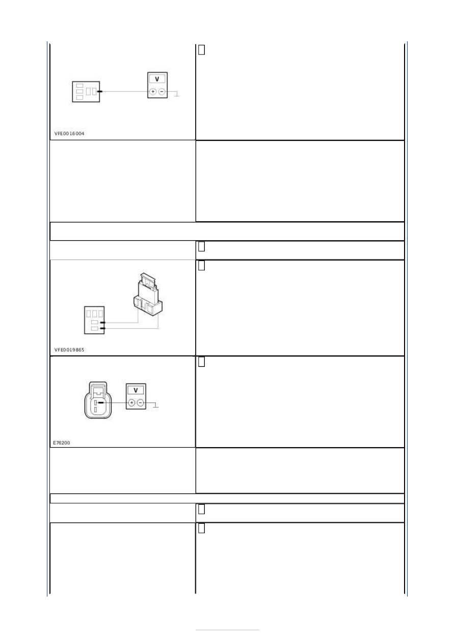
Measure the voltage between A/C clutch relay 
H401, socket C1BB03-A, pin 28, circuit SBB13A 

(RD), wiring harness side and ground. 

Does the meter display battery voltage? 
Yes 

- All except vehicles with a 2.5L engine:

GO to E7

.  

- Vehicles with a 2.5L engine

GO to E8

.  

No 

LOCATE and RECTIFY the break in circuit SBB13A 
(RD) between fuse F13 and A/C clutch relay H401 
with the aid of the Wiring Diagrams. CHECK the 
operation of the system. 

E7: CHECK THE VOLTAGE AT THE A/C CLUTCH - ALL EXCEPT VEHICLES WITH A 2.5L 
ENGINE

Disconnect Connector C1H302-C from the A/C 
clutch. 

Use a fused test cable (15 A) to bridge A/C clutch 
relay H401, socket C1BB03-A, pin 28 and pin 29, 

wiring harness side. 

Measure the voltage between the A/C clutch, 
connector C1H302-C, pin 1, circuit CH401A 

(VT/WH), wiring harness side and ground. 

Does the meter display battery voltage? 
Yes 

GO to E10

.  

No 

GO to E9

.  

E8: CHECK THE VOLTAGE AT THE A/C CLUTCH - VEHICLES WITH A 2.5L ENGINE

Disconnect Connector C1H302-A from the A/C 
clutch. 

Use a fused test cable (15 A) to bridge A/C clutch 
relay H401, socket C1BB03-A, pin 28 and pin 29, 

wiring harness side. 


Measure the voltage between the A/C clutch, 
connector C1H302-A, pin 1, circuit CH401A 

(VT/WH), wiring harness side and ground. 

Does the meter display battery voltage? 
Yes 

CHECK the mounting of the refrigerant compressor. 
If the component is securely attached, RENEW the 
A/C clutch. CHECK the operation of the system. 

No 

GO to E9

.  

E9: CHECK THE CIRCUIT BETWEEN THE A/C CLUTCH AND THE EJB FOR OPEN CIRCUIT

Disconnect Connector C1BB03-A from the EJB. 

Measure the resistance between the A/C clutch, 
connector C1H302-C (vehicles with a 2.5L engine: 

connector C1H302-A), pin 1, circuit CH401A 
(VT/WH), wiring harness side and the EJB, 
connector C1BB03-A, pin 29, circuit CH401A 
(VT/WH), wiring harness side. 

Is a resistance of less than 2 Ohms registered? 
Yes 

LOCATE and RECTIFY the break in circuit CH401A 
(VT/WH) between the EJB and A/C clutch relay 
H401 with the aid of the Wiring Diagrams. CHECK 
the operation of the system. 

No 

LOCATE and RECTIFY the break in circuit CH401A 
(VT/WH) between the EJB and the A/C clutch with 
the aid of the Wiring Diagrams. CHECK the 
operation of the system. 

E10: CHECK THE GROUND CONNECTION OF THE A/C CLUTCH

Measure the resistance between the A/C clutch, 
connector C1H302-C, pin 2, circuit GN129D 

(BK/YE), wiring harness side and ground. 

Is a resistance of less than 2 Ohms registered? 
Yes 


RENEW the air conditioning clutch. CHECK the 
operation of the system. 

No 

LOCATE and RECTIFY the break in the circuit 
between the A/C clutch and ground connection 
G1D129 with the aid of the Wiring Diagrams. 
CHECK the operation of the system. 

E11: CHECK THE PLAUSIBILITY OF THE AMBIENT TEMPERATURE

Connect the diagnostic tool. 

Using the Ford approved diagnostic tool, select 
PCM/AAT in data logger and check the ambient air 

temperature. 

Is the indicated ambient air temperature plausible? 
Yes 

GO to E12

.  

No 

GO to E51

.  

E12: CHECK THE A/C SWITCH SIGNAL 

Switch on the blower. 

Switch on the air conditioning (A/C). 

Using the Ford approved diagnostic tool, select 
BCM/AC_SW in data logger and check the A/C 

switch signal. 

Is an A/C switch signal displayed in the data logger of 
the BCM? 
Yes 

GO to E25

.  

No 

- All except vehicles with electronic automatic 
temperature control (EATC):

GO to E21

.  

- Vehicles with electronic automatic temperature 
control (EATC)

GO to E13

.  

E13: CHECK THE VOLTAGE AT THE EVAPORATOR TEMPERATURE SENSOR

Ignition switch in position 0. 

Disconnect Connector C2H406-A from the 
evaporator temperature sensor. 

Ignition switch in position II. 

Measure the voltage between the evaporator 
temperature sensor, connector C2H406-A, pin 1, 

circuit VH406A (all except vehicles with electronic 
automatic temperature control (EATC): circuit 
VH406C) (VT/BN), wiring harness side and ground. 

Is a voltage of approx. 5 volts measured? 
Yes 

GO to E18

.  

No 

- The voltage measured is more than 6 
Volts:LOCATE and RECTIFY the short to voltage in 
circuit VH406A (all except vehicles with electronic 
automatic temperature control (EATC): circuit 
VH406C) (VT/BN) between the EATC module or 
GEM and the evaporator temperature sensor with 
the aid of the Wiring Diagrams. CHECK the 


operation of the system. 
- No voltage measured:All except vehicles with 
electronic automatic temperature control 
(EATC):

GO to E14

. Vehicles with electronic 

automatic temperature control (EATC)

GO to E16

.  

E14: CHECK THE CIRCUIT BETWEEN THE EVAPORATOR TEMPERATURE SENSOR AND 
THE GEM FOR A SHORT TO GROUND

Ignition switch in position 0. 

Disconnect Connector C1BP02-C from the GEM. 

Measure the resistance between the evaporator 
temperature sensor, connector C2H406-A, pin 1, 

circuit VH406C (VT/BN), wiring harness side and 
ground. 

Is a resistance of more than 10,000 Ohms measured? 
Yes 

GO to E15

.  

No 

LOCATE and REPAIR the short to ground in circuit 
VH406C (VT/BN) between the GEM and the 
evaporator temperature sensor with the aid of the 
Wiring Diagrams. CHECK the operation of the 
system. 

E15: CHECK THE CIRCUIT BETWEEN THE EVAPORATOR TEMPERATURE SENSOR AND 
THE GEM FOR OPEN CIRCUIT

Measure the resistance between the evaporator 
temperature sensor, connector C2H406-A, pin 1, 

circuit VH406C (VT/BN), wiring harness side and 
the GEM, connector C1BP02-C, pin 2, circuit 
VH406C (VT/BN), wiring harness side. 

Is a resistance of less than 2 Ohms registered? 
Yes 

TEST the GEM and RENEW as necessary. CHECK the 
operation of the system. 

No 

LOCATE and REPAIR the break in circuit VH406C 
(VT/BN) between the evaporator temperature 
sensor and the GEM with the aid of the Wiring 
Diagrams. CHECK the operation of the system. 

E16: CHECK THE CIRCUIT BETWEEN THE EVAPORATOR TEMPERATURE SENSOR AND 
THE EATC MODULE FOR A SHORT TO GROUND

Ignition switch in position 0. 

Disconnect Connector C2H101-B from the EATC 
module. 

Measure the resistance between the evaporator 
temperature sensor, connector C2H406-A, pin 1, 

circuit VH406A (VT/BN), wiring harness side and 
ground. 


Content   ..  634  635  636  637   ..