Ford Galaxy / Ford S-MAX. Manual - part 634
 

  Index      Ford     Ford Galaxy / Ford S-MAX - service repair manual 2006 year


Search            


Content   ..  632  633  634  635   ..


Ford Galaxy / Ford S-MAX. Manual - part 634


system. 

C11: CHECK THE GROUND CONNECTION OF THE AIR CONDITIONING CONTROL 
PANEL

Ignition switch in position 0. 

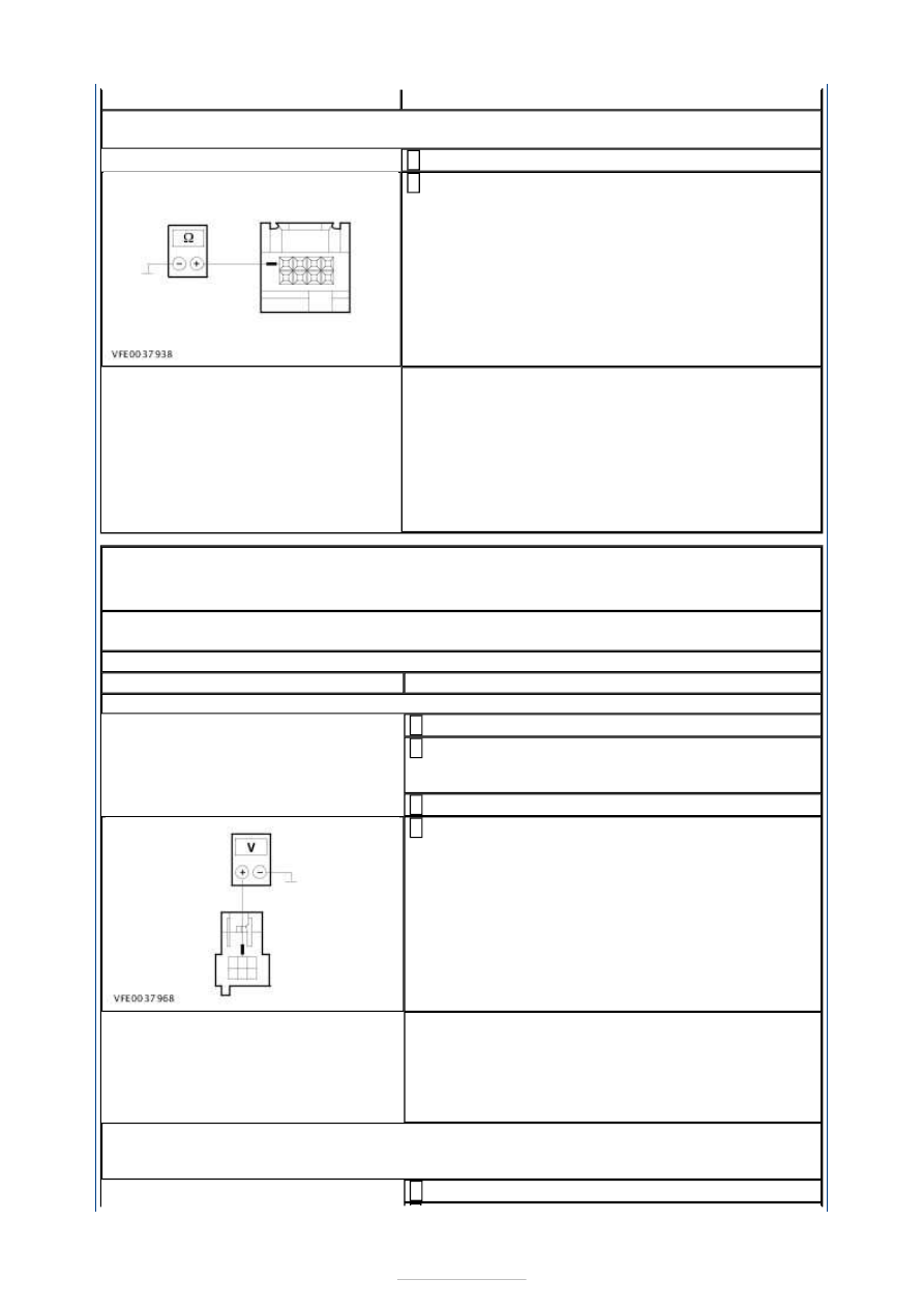
Measure the resistance between the air 
conditioning control assembly, connector C2H101-

C, pin 4, circuit GD133CS (BK), wiring harness side 
and ground. 

Is a resistance of less than 2 Ohms registered? 
Yes 

RENEW the A/C control assembly. CHECK the 
operation of the system. 

No 

LOCATE and REPAIR the open circuit between the 
air conditioning control assembly and ground 
connection G3D134 with the aid of the Wiring 
Diagrams. CHECK the operation of the system. 

PINPOINT TEST D : MALFUNCTION OF THE RECIRCULATED AIR FLAP - 
VEHICLES WITH ELECTRONIC AUTOMATIC TEMPERATURE CONTROL 
(EATC) 

NOTE: Air recirculation mode is not available when the "Defrost/demist windscreen" 
function is active. 
NOTE: Ensure that the recirculated air flap is mechanically OK. 

TEST CONDITIONS

DETAILS/RESULTS/ACTIONS

D1: TEST THE VOLTAGE AT THE RECIRCULATED AIR FLAP ACTUATOR

Ignition switch in position 0. 

Disconnect Connector C2H206 (RHD vehicles: 
connector C231CX) from the recirculated air flap 

actuator. 

Ignition switch in position II. 

Measure the voltage between the recirculated air 
flap actuator, connector C2H206 (RHD vehicles: 

connector C231CX), pin 2, circuit CH206A (YE/VT), 
wiring harness side and ground. 

Does the meter display battery voltage? 
Yes 

- LHD vehicles:

GO to D3

.  

- RHD vehicles:

GO to D4

.  

No 

GO to D2

.  

D2: CHECK CIRCUIT BETWEEN THE RECIRCULATED AIR FLAP ACTUATOR AND THE 
ELECTRONIC AUTOMATIC TEMPERATURE CONTROL (EATC) MODULE FOR OPEN 
CIRCUIT

Ignition switch in position 0. 


Disconnect Connector C2H101-B from the EATC 
module. 

Measure the resistance between the EATC module, 
connector C2H101-B, pin 14, circuit CH206A 

(YE/VT), wiring harness side and the recirculated 
air flap actuator, connector C2H206, pin 2, circuit 
CH206A (YE/VT), wiring harness side. 

Is a resistance of less than 2 Ohms registered? 
Yes 

CHECK the EATC module, if necessary INSTALL a 
new one. CHECK the operation of the system. 

No 

LOCATE and REPAIR the break in circuit CH206A 
(YE/VT) between the EATC module and the 
recirculated air flap actuator with the aid of the 
Wiring Diagrams. CHECK the operation of the 
system. 

D3: CHECK THE CIRCUITS BETWEEN THE RECIRCULATED AIR FLAP ACTUATOR AND 
THE ELECTRONIC AUTOMATIC TEMPERATURE CONTROL (EATC) MODULE FOR OPEN 
CIRCUIT - LHD VEHICLES

Ignition switch in position 0. 

Disconnect Connector C2H101-A from the EATC 
module. 

Measure the resistance between the EATC module, 
connector C2H101-A, pin 1, circuit CH207A 

(BU/GY), wiring harness side and the recirculated 
air flap actuator, connector C2H206, pin 1, circuit 
CH207A (BU/GY), wiring harness side. 

Measure the resistance between the EATC module, 
connector C2H101-A, pin 2, circuit CH208A 

(GN/OG), wiring harness side and the recirculated 
air flap actuator, connector C2H206, pin 3, circuit 
CH208A (GN/OG), wiring harness side. 

Measure the resistance between the EATC module, 
connector C2H101-A, pin 14, circuit CH209A 

(BN/YE), wiring harness side and the recirculated 
air flap actuator, connector C2H206, pin 4, circuit 
CH209A (BN/YE), wiring harness side. 


Measure the resistance between the EATC module, 
connector C2H101-A, pin 15, circuit CH210A 

(VT/WH), wiring harness side and the recirculated 
air flap actuator, connector C2H206, pin 6, circuit 
CH210A (VT/WH), wiring harness side. 

Is a resistance of less than 2 Ohms measured in all of 
the cases? 
Yes 

GO to D5

.  

No 

LOCATE and REPAIR the break in the relevant 
circuit between the air recalculation flap actuator 
and the EATC module using the Wiring Diagrams. 
CHECK the operation of the system. 

D4: CHECK THE CIRCUITS BETWEEN THE RECIRCULATED AIR FLAP ACTUATOR AND 
THE ELECTRONIC AUTOMATIC TEMPERATURE CONTROL (EATC) MODULE FOR OPEN 
CIRCUIT - RHD VEHICLES

Ignition switch in position 0. 

Disconnect Connector C2H101-A from the EATC 
module. 

Measure the resistance between the EATC module, 
connector C2H101-A, pin 1, circuit CH207B 

(BU/GY), wiring harness side and the recirculated 
air flap actuator, connector C2H101-A, pin 4, 
circuit CH207B (BU/GY), wiring harness side. 

Measure the resistance between the EATC module, 
connector C2H101-A, pin 2, circuit CH208B 

(GN/OG), wiring harness side and the recirculated 
air flap actuator, connector C2H101-A, pin 6, 
circuit CH208B (GN/OG), wiring harness side. 

Measure the resistance between the EATC module, 
connector C2H101-A, pin 14, circuit CH209B 


(GY/RD), wiring harness side and the recirculated 
air flap actuator, connector C2H101-A, pin 1, 
circuit CH209B (GY/RD), wiring harness side. 

Measure the resistance between the EATC module, 
connector C2H101-A, pin 15, circuit CH210B 

(VT/WH), wiring harness side and the recirculated 
air flap actuator, connector C2H101-A, pin 3, 
circuit CH210B (VT/WH), wiring harness side. 

Is a resistance of less than 2 Ohms measured in all of 
the cases? 
Yes 

GO to D5

.  

No 

LOCATE and REPAIR the break in the relevant 
circuit between the air recalculation flap actuator 
and the EATC module using the Wiring Diagrams. 
CHECK the operation of the system. 

D5: CHECK THE CIRCUITS BETWEEN THE AIR RECIRCULATION FLAP ACTUATOR AND 
THE EATC MODULE FOR SHORT TO VOLTAGE

Ignition switch in position II. 

Measure the voltage between the EATC module, 
connector C2H101-A, pin 1, circuit CH207A 

(BU/GY) (RHD vehicles: circuit CH207B (BU/GY)), 
wiring harness side and ground. 

Measure the voltage between the EATC module, 
connector C2H101-A, pin 2, circuit CH208A 

(GN/OG) (RHD vehicles: circuit CH208B (GN/OG)), 
wiring harness side and ground. 

Measure the voltage between the EATC module, 
connector C2H101-A, pin 14, circuit CH209A 

(BN/YE) (RHD vehicles: circuit CH209B (BN/YE)), 
wiring harness side and ground. 

Measure the voltage between the EATC module, 
connector C2H101-A, pin 15, circuit CH210A 

(VT/WH) (RHD vehicles: circuit CH210B (VT/WH)), 
wiring harness side and ground. 

Is a voltage measured during one or more 
measurements? 
Yes 


Content   ..  632  633  634  635   ..