Ford Galaxy / Ford S-MAX. Manual - part 635
LOCATE and REPAIR the short to voltage in the
relevant circuit(s) between the air recirculation flap
actuator and the EATC module using the Wiring
Diagrams. CHECK the operation of the system.
No
GO to D6
.
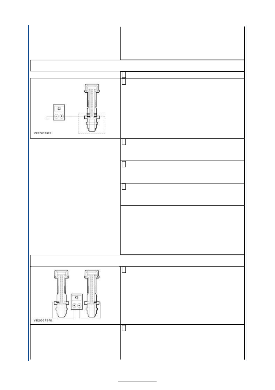
D6: CHECK THE CIRCUITS BETWEEN THE AIR RECIRCULATION FLAP ACTUATOR AND
THE EATC MODULE FOR SHORT TO GROUND
Ignition switch in position 0.
1
Measure the resistance between the EATC module,
connector C2H101-A, pin 1, circuit CH207A
(BU/GY) (RHD vehicles: circuit CH207B (BU/GY)),
wiring harness side and ground.
2
Measure the resistance between the EATC module,
connector C2H101-A, pin 2, circuit CH208A
(GN/OG) (RHD vehicles: circuit CH208B (GN/OG)),
wiring harness side and ground.
3
Measure the resistance between the EATC module,
connector C2H101-A, pin 14, circuit CH209A
(BN/YE) (RHD vehicles: circuit CH209B (BN/YE)),
wiring harness side and ground.
4
Measure the resistance between the EATC module,
connector C2H101-A, pin 15, circuit CH210A
(VT/WH) (RHD vehicles: circuit CH210B (VT/WH)),
wiring harness side and ground.
5
Is a resistance of more than 10,000 Ohms measured
in all of the measurements?
Yes
GO to D7
.
No
LOCATE and REPAIR the short to ground in the
relevant circuit(s) between the air recirculation flap
actuator and the EATC module using the Wiring
Diagrams. CHECK the operation of the system.
D7: CHECK THE CIRCUITS BETWEEN THE AIR RECIRCULATION FLAP ACTUATOR AND
THE EATC MODULE FOR SHORT CIRCUIT
Measure the resistance between the EATC module,
connector C2H101-A, pin 1, circuit CH207A
(BU/GY) (RHD vehicles: circuit CH207B (BU/GY)),
wiring harness side and the EATC module,
connector C2H101-B, pin 14, circuit CH206A
(BN/YE), wiring harness side..
1
Measure the resistance between the EATC module,
connector C2H101-A, pin 1, circuit CH207A
(BU/GY) (RHD vehicles: circuit CH207B (BU/GY)),
wiring harness side and the EATC module,
connector C2H101-A, pin 2, circuit CH208A
(BN/YE) (RHD vehicles: circuit CH208B (BN/YE)),
2