Ford Galaxy / Ford S-MAX. Manual - part 633
 

  Index      Ford     Ford Galaxy / Ford S-MAX - service repair manual 2006 year


Search            


Content   ..  631  632  633  634   ..


Ford Galaxy / Ford S-MAX. Manual - part 633


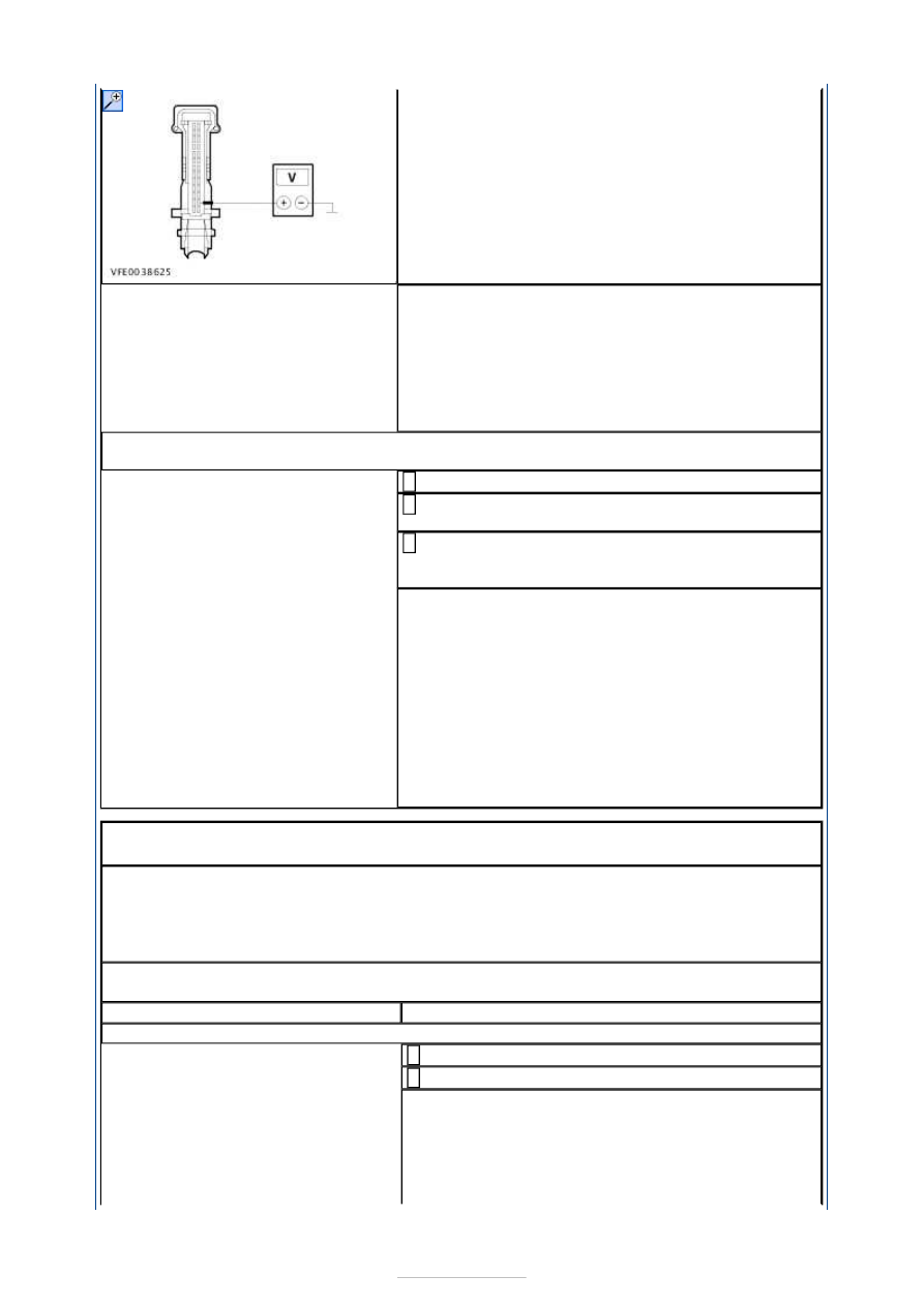
Is a voltage measured? 
Yes 

GO to B22

.  

No 

RENEW the blower control module. CHECK the 
operation of the system. If the system is still not 
working, CHECK the EATC module and INSTALL A 
NEW ONE if necessary. 

B22: CHECK THE CIRCUIT BETWEEN THE BLOWER CONTROL MODULE AND THE 
BLOWER MOTOR FOR A SHORT TO GROUND

Ignition switch in position 0. 

Disconnect Connector C2H123-B from the blower 
motor. 

Measure the resistance between the blower control 
module, connector C2H123-A, pin 1, circuit 

VH301A (YE/BU), wiring harness side and ground. 

Is a resistance of more than 10,000 Ohms measured? 
Yes 

RENEW the blower control module. CHECK the 
operation of the system. If the system is still not 
working, CHECK the EATC module and INSTALL A 
NEW ONE if necessary. 

No 

LOCATE and REPAIR the short to ground in circuit 
VH301A (YE/BU) between the blower control 
module and the blower motor with the aid of the 
Wiring Diagrams. CHECK the operation of the 
system. 

PINPOINT TEST C : MALFUNCTION OF THE RECIRCULATED AIR FLAP - 
VEHICLES WITH MANUAL AIR CONDITIONING 

NOTE: The recirculated air flap is actuated by means of a DC motor. This motor is 
actuated by the electronic automatic temperature control (EATC) module or automatic 
temperature control (ATC) module for a maximum of 7 seconds after pressing the air 
recirculation button. Opening and closing of the air recirculation flap is performed by 
reversing the polarity of the applied voltage. 
NOTE: Recirculated air mode is not available when the "Defrost/demist windscreen" 
function is active. 

TEST CONDITIONS

DETAILS/RESULTS/ACTIONS

C1: CHECK FUSE F27

Ignition switch in position 0. 

CHECK Fuse F27 (CJB). 

Is the fuse OK? 
Yes 

GO to C2

.  

No 

RENEW fuse F27 (10 A). CHECK the operation of 
the system. If the fuse blows again, LOCATE and 


REPAIR the short using the Wiring Diagrams. 

C2: CHECK THE VOLTAGE AT FUSE F27

Connect Fuse F27 (CJB). 

Measure the voltage between fuse F27 (10 A) and 
ground. 

Does the meter display battery voltage? 
Yes 

GO to C5

.  

No 

REPAIR the voltage supply to fuse F27 with the aid 
of the Wiring Diagrams. CHECK the operation of 
the system. 

C3: CHECK FUSE F4

CHECK Fuse F4 (CJB). 

Is the fuse OK? 
Yes 

GO to C4

.  

No 

RENEW fuse F4 (7.5 A). CHECK the operation of 
the system. If the fuse blows again, LOCATE and 
REPAIR the short using the Wiring Diagrams. 

C4: CHECK THE VOLTAGE AT FUSE F4

Connect Fuse F4 (CJB). 

Ignition switch in position II. 

Measure the voltage between fuse F4 (7.5 A) and 
ground. 

Does the meter display battery voltage? 
Yes 

GO to C5

.  

No 

REPAIR the voltage supply to fuse F4 with the aid 
of the Wiring Diagrams. CHECK the operation of 
the system. 

C5: CHECK THE VOLTAGE AT THE RECIRCULATED AIR FLAP ACTUATOR

Ignition switch in position 0. 

Disconnect Connector C5H206 (RHD vehicles: 
Connector C5H206 from the recirculated air flap 

actuator. 

Ignition switch in position II. 

Measure the voltage at the recirculated air flap 
actuator, connector C5H206 (RHD vehicles: 

connector C6H206), between pin 2 and pin 4, 
wiring harness side. 

Actuate the recirculated air switch several times 
during the measurement. 

Is a voltage of at least 10 V measured with alternating 
polarity? 
Yes 

CHECK the air recirculation flap for ease of 
movement and correct operation. If the air 
recirculation flap is OK, RENEW the air recirculation 


flap actuator. CHECK the operation of the system. 

No 

GO to C6

.  

C6: CHECK FOR OPEN CIRCUIT BETWEEN THE AIR RECIRCULATION FLAP ACTUATOR 
AND THE A/C CONTROL ASSEMBLY

Ignition switch in position 0. 

Disconnect Connector C2H101-C from the air 
conditioning control assembly. 

Measure the resistance between the recirculated 
air flap actuator, connector C5H206, pin 2 (RHD 

vehicles: connector C6H206, pin 4), circuit CH207C 
(BU/GY), wiring harness side and the air 
conditioning control assembly, connector C2H101-
C, pin 7, circuit CH207C (BU/GY), wiring harness 
side. 

Measure the resistance between the recirculated 
air flap actuator, connector C5H206, pin 4 (RHD 

vehicles: connector C6H206, pin 2), circuit CH208C 
(GN/OG), wiring harness side and the air 
conditioning control assembly, connector C2H101-
C, pin 6, circuit CH208C (GN/OG), wiring harness 
side. 

Is a resistance of less than 2 Ohms measured in both 
cases? 
Yes 

GO to C7

.  

No 

LOCATE and REPAIR the break in the 
corresponding circuit between the recirculated air 
flap actuator and the air conditioning control 
assembly with the aid of the Wiring Diagrams. 
CHECK the operation of the system. 

C7: CHECK THE VOLTAGE AT THE AIR CONDITIONING CONTROL ASSEMBLY (PIN 1)

Measure the voltage between the air conditioning 
control assembly, connector C2H101-C, pin 1, 

circuit CBP27C (BU/RD), wiring harness side and 
ground. 

Does the meter display battery voltage? 
Yes 

GO to C9

.  

No 

GO to C8

.  

C8: CHECK FOR OPEN CIRCUIT BETWEEN THE AIR CONDITIONING CONTROL 
ASSEMBLY AND THE CJB

Disconnect Connector C1BP02-C from the CJB. 

Measure the resistance between the air 
conditioning control assembly, connector C2H101-


C, pin 1, circuit SBP27C (BU/RD), wiring harness 
side and the CJB, connector C1BP02-C, pin 74, 
circuit SBP27C (BU/RD), wiring harness side. 

Is a resistance of less than 2 Ohms registered? 
Yes 

CHECK the CJB and RENEW as necessary. CHECK 
the operation of the system. 

No 

LOCATE and RECTIFY the break in circuit SBP27C 
(BU/RD) between the air conditioning control 
assembly and the CJB with the aid of the Wiring 
Diagrams. CHECK the operation of the system. 

C9: CHECK THE VOLTAGE AT THE AIR CONDITIONING CONTROL ASSEMBLY (PIN 8)

Ignition switch in position II. 

Measure the voltage between the air conditioning 
control assembly, connector C2H101-C, pin 8, 

circuit CBP04 (VT), wiring harness side and ground. 

Does the meter display battery voltage? 
Yes 

GO to C11

.  

No 

GO to C10

.  

C10: CHECK FOR OPEN CIRCUIT BETWEEN THE AIR CONDITIONING CONTROL 
ASSEMBLY AND THE CJB

Ignition switch in position 0. 

Disconnect Connector C1BP02-C from the CJB. 

Measure the resistance between the air 
conditioning control assembly, connector C2H101-

C, pin 8, circuit CBP04 (VT), wiring harness side 
and the CJB, connector C1BP02-C, pin 68, circuit 
CBP04T (VT), wiring harness side. 

Is a resistance of less than 2 Ohms registered? 
Yes 

CHECK the CJB and RENEW as necessary. CHECK 
the operation of the system. 

No 

LOCATE and RECTIFY the open circuit between the 
air conditioning control assembly and the CJB using 
the Wiring Diagrams. CHECK the operation of the 


Content   ..  631  632  633  634   ..