Ford Galaxy / Ford S-MAX. Manual - part 631
 

  Index      Ford     Ford Galaxy / Ford S-MAX - service repair manual 2006 year


Search            


Content   ..  629  630  631  632   ..


Ford Galaxy / Ford S-MAX. Manual - part 631


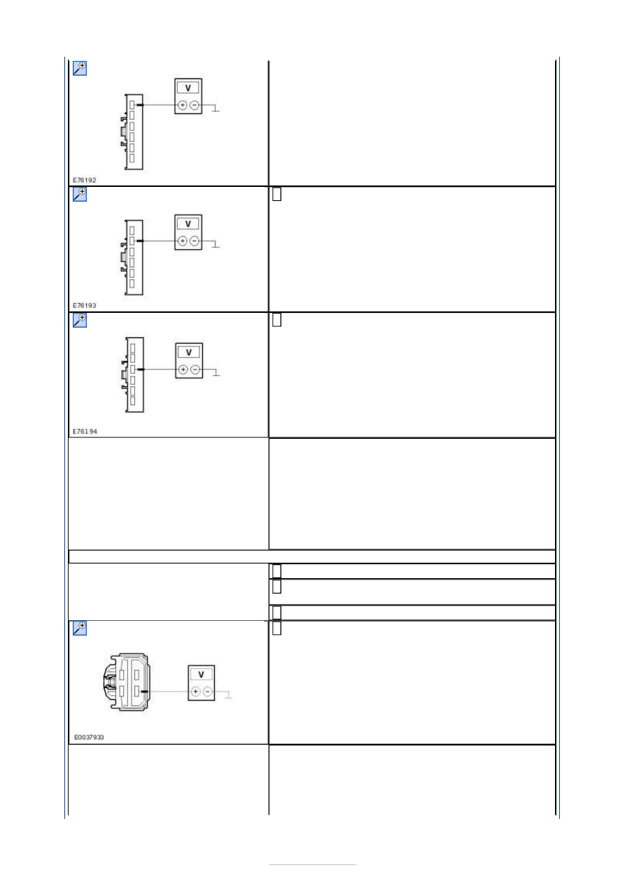
Measure the voltage between the blower switch, 
connector C2H426, pin 2, circuit CH428A (GN/WH), 

wiring harness side and ground. 

Measure the voltage between the blower switch, 
connector C2H426, pin 3, circuit CH429A (GY/BN), 

wiring harness side and ground. 

Is battery voltage measured in all cases? 
Yes 

RENEW the blower switch. CHECK the operation of 
the system. 

No 

- Battery voltage not measured in one/two 
cases:

GO to A17

.  

- Battery voltage not measured in any case:

GO to 

A16

.  

A16: CHECK THE VOLTAGE AT THE BLOWER RESISTOR

Ignition switch in position 0. 

Disconnect Connector C2H434 from the blower 
resistor. 

Ignition switch in position II. 

Measure the voltage between the blower resistor, 
connector C2H434, pin 4, circuit CBB28C (WH/VT), 

wiring harness side and ground. 

Does the meter display battery voltage? 
Yes 

INSTALL a new heater blower series resistor. 
CHECK the operation of the system. 

No 


LOCATE and REPAIR the break in circuit CBB28C 
(WH/VT) between the blower resistor and soldered 
connection SP175 with the aid of the Wiring 
Diagrams. CHECK the operation of the system. 

A17: CHECK THE CIRCUITS BETWEEN THE BLOWER RESISTOR AND THE BLOWER 
SWITCH FOR OPEN CIRCUIT

Ignition switch in position 0. 

Disconnect Connector C2H434 from the blower 
resistor. 

Measure the resistance between the blower resistor 
assembly, connector C2H434, pin 2, circuit CH427A 

(BN), wiring harness side and the blower switch, 
connector C2H426, pin 1, circuit CH427A (BN), 
wiring harness side. 

Measure the resistance between the blower 
resistor, connector C2H434, pin 4, circuit CH428A 

(GN/WH), wiring harness side and the blower 
switch, connector C2H426, pin 1, circuit CH428A 
(GN/WH), wiring harness side. 

Measure the resistance between the blower 
resistor, connector C2H434, pin 3, circuit CH429A 

(GY/BN), wiring harness side and the blower switch, 
connector C2H426, pin 3, circuit CH428A (GY/BN), 
wiring harness side. 

Is a resistance of less than 2 Ohms measured in all of 
the cases? 
Yes 

INSTALL a new heater resistor. CHECK the 
operation of the system. 

No 

LOCATE and RECTIFY the break in the affected 
circuit with the aid of the Wiring Diagrams. CHECK 
the operation of the system. 

PINPOINT TEST B : BLOWER MOTOR INOPERATIVE/INCORRECT 
FUNCTION - VEHICLES WITH ELECTRONIC AUTOMATIC TEMPERATURE 
CONTROL 

TEST CONDITIONS

DETAILS/RESULTS/ACTIONS

B1: CHECK THE OPERATION OF THE BLOWER MOTOR

Ignition switch in position II. 

Test all of the speeds of the heater blower motor. 

Is the blower motor inoperative in all speed settings? 
Yes 

GO to B2

.  


No 

GO to B20

.  

B2: CHECK FUSE F28

Ignition switch in position 0. 

CHECK Fuse F28 (EJB). 

Is the fuse OK? 
Yes 

GO to B3

.  

No 

RENEW fuse F28 (40 A). CHECK the operation of 
the system. If the fuse blows again, LOCATE and 
REPAIR the short using the Wiring Diagrams. 

B3: CHECK THE VOLTAGE AT FUSE F28

Connect Fuse F28 (EJB). 

Measure the voltage between fuse F28 (40 A) and 
ground. 

Does the meter display battery voltage? 
Yes 

GO to B4

.  

No 

REPAIR the voltage supply to fuse F28 with the aid 
of the Wiring Diagrams. CHECK the operation of the 
system. 

B4: CHECK FUSE F18

CHECK Fuse F18 (CJB). 

Is the fuse OK? 
Yes 

GO to B5

.  

No 

RENEW fuse F18 (5 A). CHECK the operation of the 
system. If the fuse blows again, LOCATE and 
REPAIR the short using the Wiring Diagrams. 

B5: CHECK THE VOLTAGE AT FUSE F18

Connect Fuse F18 (CJB). 

Ignition switch in position II. 

Measure the voltage between fuse F18 (5 A) and 
ground. 

Does the meter display battery voltage? 
Yes 

GO to B6

.  

No 

CHECK the CJB and RENEW as necessary. CHECK 
the operation of the system. 

B6: CHECK THE ELECTRONIC AUTOMATIC TEMPERATURE CONTROL (EATC) MODULE

Ignition switch in position 0. 

Disconnect Connector C2H101-B from the EATC 
module. 

Ignition switch in position II. 

Does the blower motor run at its highest speed setting? 
Yes 

CHECK the EATC module, if necessary INSTALL a 
new one. CHECK the operation of the system. 

No 

GO to B7

.  

B7: CHECK VOLTAGE AT BLOWER MOTOR

Disconnect Connector C2H123-B from the blower 
motor. 

Ignition switch in position II. 

Measure the voltage between the blower motor, 
connector C2H123-B, pin 1, circuit CBB28A 

(GY/VT), wiring harness side and ground. 

Does the meter display battery voltage? 
Yes 

GO to B14

.  

No 

GO to B8

.  

B8: CHECK THE VOLTAGE AT THE BLOWER RELAY H402 

Ignition switch in position 0. 

Disconnect Blower relay H402 from socket C1BB01-
A. 

Measure the voltage between the blower relay 
H402, socket C1BB01-A, pin 36, circuit CBB28A 

(RD/GN), wiring harness side and ground. 

Does the meter display battery voltage? 
Yes 

GO to B9

.  

No 

LOCATE and REPAIR the break in circuit CBB28A 
(RD/GN) between blower relay H402 and fuse F28 
with the aid of the Wiring Diagrams. CHECK the 
operation of the system. 

B9: CHECK THE VOLTAGE AT THE BLOWER RELAY H402 

Measure the voltage between the blower relay, 
socket C1BB01-A, pin 39, circuit SBB33E (RD), 

wiring harness side and ground. 

Does the meter display battery voltage? 
Yes 

GO to B10

.  

No 

LOCATE and REPAIR the break in the circuit 
between blower relay H402 and fuse F33 using the 
Wiring Diagrams. CHECK the operation of the 
system. 


Content   ..  629  630  631  632   ..