Ford Galaxy / Ford S-MAX. Manual - part 477
 

  Index      Ford     Ford Galaxy / Ford S-MAX - service repair manual 2006 year


Search            


Content   ..  475  476  477  478   ..


Ford Galaxy / Ford S-MAX. Manual - part 477


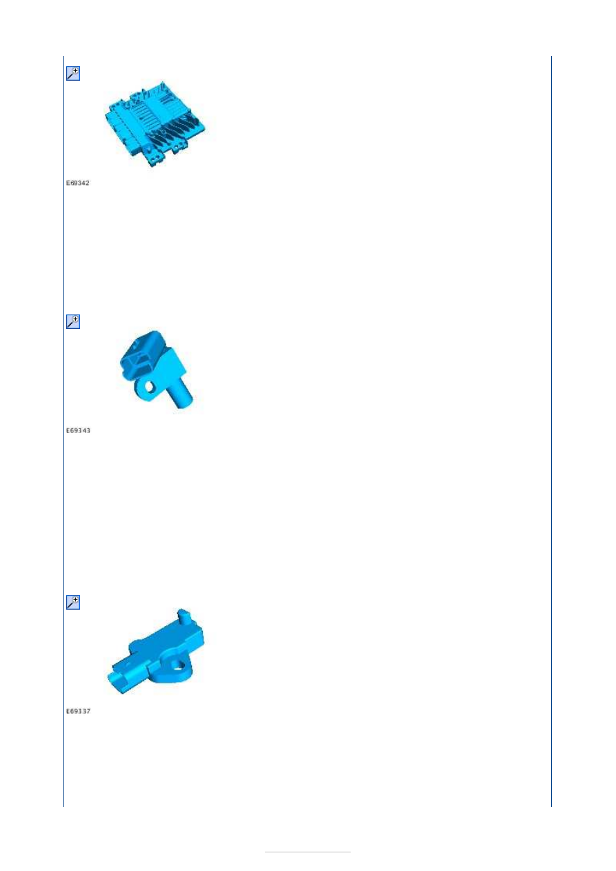
The PCM is attached to the windshield washer reservoir and has 3 electrical connectors with 
a total of 128 pins. 

The PCM monitors and processes the signals from the sensors. The fuel injectors, the fuel 
metering valve and the fuel pressure regulator are also controlled by the PCM. 

The PCM can be diagnosed through the data link connector (DLC) using the Worldwide 
Diagnostic System (WDS). 

CMP sensor 

The CMP sensor uses the Hall effect principle and is supplied with a reference voltage of 5 
V. 

During starting, the CKP sensor and the CMP sensor are synchronized. If both signals are 
present, the engine can be started. 

If the signal from the CMP sensor fails while the engine is running, the engine continues to 
run using the signals from the CKP sensor. 

If the CMP signal is missing at the next starting operation, it will not be possible to start the 
engine. 

CKP sensor 

The CKP sensor is an inductive pulse generator which scans 36-1 cast protrusions on the 
flywheel. Minus one means that one of the cast protrusions is missing and this gap is 
located at 90 degrees before top dead centre. This gap is used by the PCM as a reference 
for crankshaft position. 

The CKP sensor uses the Hall effect principle. 


ECT sensor 

The ECT sensor is screwed directly into the coolant outlet connector and measures the 
temperature of the engine coolant rather than the cylinder head temperature. The 
information is used by the instrument cluster for the temperature gauge indication. It is 
also used by the PCM to calculate fuel injection timing and period of injection which will 
vary dependant on the engine temperature. 

Fuel pressure regulator 

The fuel pressure regulator is screwed directly onto the high-pressure outlet of the fuel 
pump. 

The fuel pressure regulator regulates the fuel pressure at the high-pressure outlet and 
thereby the fuel pressure to the fuel rail. 

In addition, the fuel pressure regulator dampens fuel pressure fluctuations which arise 
when the fuel pump is supplying fuel and as a result of the fuel injection process. 

Fuel metering valve 

The fuel metering valve adjusts the quantity of fuel to the high-pressure pump elements as 
a function of engine operating conditions. This improves engine efficiency. 

The fuel metering valve is controlled by the PCM using pulse-width modulation. 

The fuel metering valve is closed when de-energized. 

EOP sensor 


The EOP sensor is located in the oil filer housing. The EOP is connected to the instrument 
cluster and is not directly part of the electronic engine control system. The EOP sensor 
registers engine oil pressure. The sensor opens when a defined pressure is reached and the 
engine oil pressure warning light is illuminated on the instrument cluster. 

FRP sensor 

The FRP sensor is located in the fuel rail and measures the fuel pressure within the fuel 
system. 

The FRP sensor consists of a piezoelectric element that sends a variable voltage signal to 
the PCM, as a function of fuel pressure. 

The PCM uses this signal to calculate how long the fuel injectors are to be actuated for and 
to regulate the fuel pressure by means of the fuel pressure regulator. 

Brake pedal position (BPP) switch and brake light switch 

The BPP switch is connected to the instrument cluster through the CAN bus. 


The BPP switch is closed when de-energized and sends a ground signal to the PCM. 

The brake light switch is connected with the PCM through a conventional electrical 
connector. 

The brake light switch is open when de-energized. When the brake light switch is closed, it 
sends 12 volts to the PCM. 

The signals of the BPP switch and the brake light switch are used if the accelerator pedal 
position (APP) sensor should fail. 

In this instance, the PCM compares the signals of the BPP switch and brake light switch. 

APP sensor 

The APP sensor is a double contactless inductive sensor. 

For safety reasons, the APP sensor consists of two sensors. 

If the APP sensor malfunctions when the vehicle is in operation, a diagnostic trouble code 
(DTC) will be stored in the PCM. 

If one of the sensors in the APP sensor should fail, the engine will operate at reduced 
power. 

If the vehicle is fitted with a driver information system, the fault message "REDUCED 
ACCELERATION" will be displayed. 

If both sensors of the APP switch fail, after a single operation of the BPP switch and the 
brake light switch and then after a plausibility check, the engine is controlled up to a speed 
of 1200 RPM. The vehicle can be accelerated to a maximum speed of 56 km/h (35 mph). 

When the BPP switch and the brake light switch are actuated again, engine speed will drop 
to idle speed. Once the BPP switch and the brake light switch are de-energized again, 
engine speed is increased again. 

If the vehicle is fitted with an information and message system, the fault message 
"REDUCED TOP SPEED" will be displayed. 

If the vehicle is not fitted with an information and message system, the malfunction 
indicator lamp (MIL) will be illuminated to indicate a system fault. 


Content   ..  475  476  477  478   ..