Ford Galaxy / Ford S-MAX. Manual - part 393
Fuel Charging and Controls -
Turbocharger - 2.5L Duratec
(162kW/220PS) - VI5 - Turbocharger
S-MAX/Galaxy 2006.5 (02/2006-)
Diagnosis and Testing
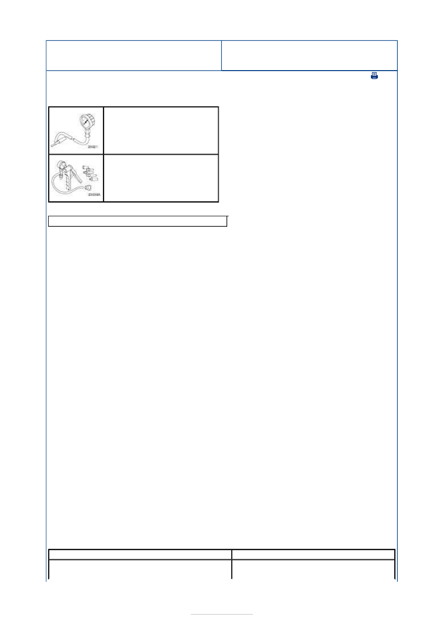
Special Tool(s)
General Equipment
Principles of Operation
The turbocharger is governed by a wastegate control valve. The wastegate control valve
redirects some of the exhaust gas past the turbine and therefore acts as a governor. The
wastegate control valve is preset during manufacture and must not be tampered with.
The intake air system is fitted with a turbocharger pressure release valve. This vents the
intake air system when the throttle is closed and recirculates the air back into the intake air
system. It also releases pressure on the turbocharger which will reduce turbo lag and will
improve acceleration and increase engine performance.
The turbocharger is equipped with a boost control system. The powertrain control module
(PCM) detects 1st or 2nd gear using the engine speed and vehicle speed signals. This
information is then used to adjust the pressures applied to the wastegate control valve
allowing it to open at a lower boost pressure. This prevents the turbocharger developing
maximum boost in 1st and 2nd gears.
Inspection and Verification
NOTE: It is normal for a small amount of combustion gas to pass into the crankcase. This
gas is scavenged into the air intake system through the positive crankcase ventilation
(PCV) system, which incorporates an crankcase vent oil separator. Some engine oil, in the
form of a vapor is carried into the air intake system with the blow-by gases (this engine
oil also contributes to valve seat durability). This means that oil will collect inside the air
intake components and the turbocharger. This is not an indication that the turbocharger
oil seal has failed. The turbocharger oil seal will not fail unless the bearings fail first,
which will cause the turbocharger to become noisy or seize. Do not install a new
turbocharger due to oil inside the turbocharger or the air intake components. If a leak is
detected in the oil supply or return tubes or connections, locate and rectify the source. Do
not install a new turbocharger due to an oil leak.
1. 1. Verify the customer concern.
2. 2. Visually inspect for obvious signs of mechanical or electrical damage.
Visual Inspection Chart
Boost Pressure Gauge
310-020 (23-021)
Hand Vacuum/Pressure Pump
416-D001 (23-036A)
Ford diagnostic equipment
Mechanical
Electrical
Oil leak(s)
Coolant leak(s)
Wiring harness(es)
Electrical connector(s)