Ford Galaxy / Ford S-MAX. Manual - part 286
 

  Index      Ford     Ford Galaxy / Ford S-MAX - service repair manual 2006 year


Search            


Content   ..  284  285  286  287   ..


Ford Galaxy / Ford S-MAX. Manual - part 286


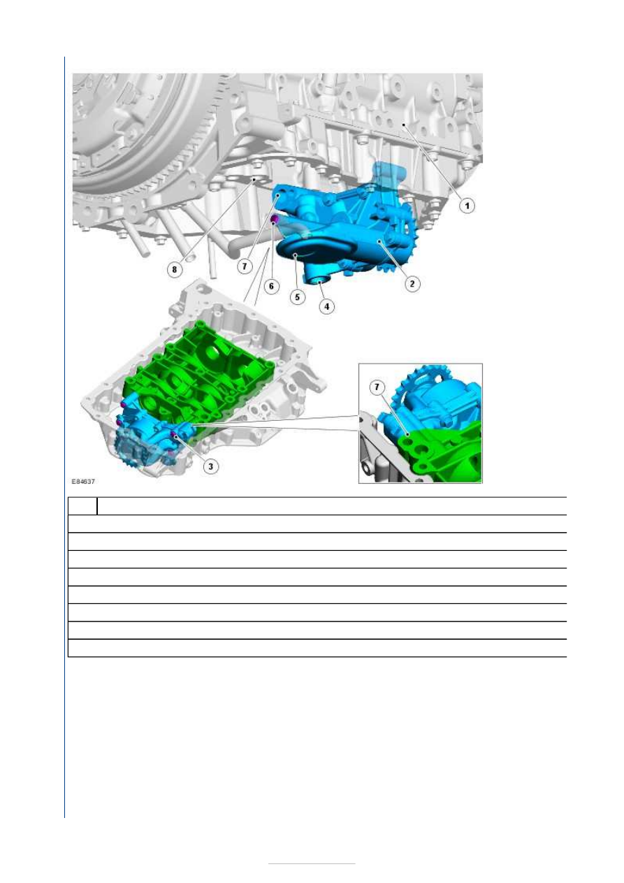
Description 

Cylinder block 

Oil Pump Assembly 

Retaining bolt (4 pieces) 

Pressure relief valve housing 

Oil pick up and strainer 

Mounting bolt (1 off) 

Oil pump outlet port 

Oil pump supply to cylinder block 

The oil pump is designed as a rotor pump and is bolted to the balance shaft unit using four retaining bolts. A further bolt at 
the oil strainer secures the oil pump with the oil dipstick tube. 

The drive is provided by the crankshaft via a Simplex chain. 

The oil pump generates a maximum permissible oil pressure of approx. 6.5 bar and a maximum delivery rate of 50 l/min.

A pressure relief valve within the oil pump outlet protects the oil pump and lubrication system components from system over
pressure. 

The pressure relief valve opens at approx. 8 bar. The excess oil runs directly back into the oil pan.

Oil filter/oil cooler unit 

Item

1

2

3

4

5

6

7

8


Description 

Coolant return 

Oil filter housing 

Oil pressure switch 

Oil cooler 

Coolant feed 

The oil filter/oil cooler unit is located on the intake side of the engine, level with the third cylinder.

The oil filter element (paper filter element) is located in the oil filter housing. 

The coolant is routed from the cylinder block into the oil cooler via the coolant feed. The coolant is routed to the thermostat 
housing of the cooling system via the coolant return. 

Intake manifold 

The intake manifold is designed so that the charge air is routed to all eight intake ducts in a controlled manner.

Furthermore, the gas from the positive crankcase ventilation system and from the 

EGR (exhaust gas recirculation)

returned to the intake manifold. 

The seal with the intake ducts at the cylinder head is provided: 

by means of one O-ring for each of the four lower swirl ducts,  
by means of one rubber seal for each of the four upper charge ducts. 

Note: When fitting the intake manifold, ensure that the O-rings/rubber seals are seated correctly.

The intake manifold is bolted to the cylinder head using a total of seven retaining bolts. 

Item

1

2

3

4

5


Intake ducts 


Description 

Charge duct (in the upper part of the cylinder head) 

Intake manifold 

Swirl duct 

Outlet Duct 

Charge duct (in the lower part of the cylinder head) 

The movement of the air flowing into the cylinder is crucial for optimum mixture formation. 

Each cylinder is equipped with two intake valves. Leading to each intake valve is 

one swirl duct and  
one charge duct. 

The swirl duct produces a specific rotational movement (swirl) in the charge air. This optimises mixture formation in the 
lower engine speed range and thus reduces fuel consumption. 

The charge duct guarantees an optimum cylinder charge at all times. This has a positive effect on engine performance in 
the upper engine speed range

Exhaust Manifolds 

Item

1

2

3

4

5


Description 

Spacer 

Exhaust Manifolds 

Gasket 

EGR

 connection 

TC (turbocharger)

 connecting flange 

Self-locking retaining nut 

The exhaust manifold is bolted to the cylinder head using nine studs with self-locking nuts. 

There is also a spacer mounted over each stud. The spacers compensate the expansion play when the exhaust manifold 
heats up or cools down. 

One connecting flange each is incorporated in the exhaust manifold for the 

TC

 and the 

EGR

There is an exhaust manifold heat shield mounted over the exhaust manifold (not illustrated). This protects heat
components in the vicinity of the exhaust manifold. It also prevents burns if someone accidentally touches the exhaust parts.

TC


Description 

Item

1

2

3

4

5

6

Item


Content   ..  284  285  286  287   ..