Ford Galaxy / Ford S-MAX. Manual - part 284
 

  Index      Ford     Ford Galaxy / Ford S-MAX - service repair manual 2006 year


Search            


Content   ..  282  283  284  285   ..


Ford Galaxy / Ford S-MAX. Manual - part 284


The intake camshaft is driven by the exhaust camshaft via a timing chain. 

Pretensioning of the timing chain is performed by a hydraulic timing chain tensioner. 

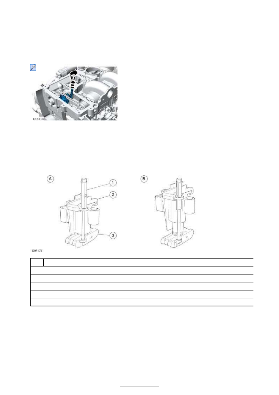
Hydraulic timing chain tensioner 

The hydraulic timing chain tensioner is mounted between the camshaft sprockets on the upper part of the cylinder head.

The hydraulic chain tensioner is supplied with the appropriate oil pressure via an oil bore. Also integrated in the hydraulic 
timing chain tensioner is a compression spring. This ensures the necessary pretensioning of the drive chain.

There is a service pin at the chain tensioner for releasing the pretension during servicing. 

Locking and disengaging the hydraulic timing chain tensioner 


Description 

Chain tensioner locked 

Chain tensioner disengaged 

Service pin 

Upper chain guide 

Lower chain guide 

NOTE: After installing the upper part of the cylinder head, make sure that the hydraulic chain tensioner is in the 
disengaged position. 

The chain tensioner can be locked and disengaged again for servicing using the service pin. 

To lock the chain tensioner, lift the service pin and then turn it 90 degrees. 

To pretension the chain tensioner, turn the service pin once more by 90 degrees. The unlocking can be clearly felt.

Cylinder block 

Item

A

B

1

2

3


NOTE: Cylinder 1 is located on the transaxle side of the engine. 

The cylinder block is made from grey cast iron and is double-walled. This helps to achieve high strength. It also forms a 
blanket of air that results in considerable sound insulation. 

The serial number of the engine and the engine code are located on the intake side of the cylinder block (in line with the 
second cylinder). 

The running surfaces of the cylinders are worked directly into the cylinder block. 

There are two holes on the cylinder block for the guide bushings for securing the cylinder head gasket and the cylinder head.

Oil Spray Jets 


Description 

Oil spray nozzle retaining bolt 

Oil spray jet (4 off) 

The efficient combustion provided by the direct-injection turbocharged diesel engine means that high temperatures are 
transmitted to the pistons. 

There is an oil spray nozzle installed at the lower end of each cylinder liner for cooling the pistons. The oil spray nozzles spray 
engine oil in a targeted manner under the piston crowns. 

There are oil passages integrated in the piston crowns. The sprayed engine oil enters these oil passages and thus ensures the 
necessary piston cooling. Piston cooling is not essential when the engine is cold. Lubrication of the crank gear and camshaft 
has a higher priority here. For this reason, the oil spray nozzles only open if an oil pressure of more than 0.5 bar is present at 
them. 

Cylinder block extension 

Item

1

2


The oil pan extension is fitted between the cylinder block and the oil pan. 

The use of balance shafts means that the oil pump has to be moved further in the direction of the oil pan. This reduces the 
distance from the oil pump to the oil pan. The cylinder block extension at the cylinder block re-
between the oil pump and oil pan. 

The seal with the cylinder block and the oil pan is formed using sealing compound. 

Crankshaft and main bearings 


Description 

Flywheel side 

Top thrust washers (2 pieces) 

Top crankshaft bearing shells (5 pieces) 

Bottom crankshaft bearing shells (5 pieces) 

Balance shaft drive gear 

Lower thrust washers (2 pieces) 

The crankshaft runs on five bearings by means of five main bearing caps. 

Each main bearing half cap is stamped with the corresponding cylinder number for identification.

The crankshaft's radial play is restricted by four semicircular thrust washers that are arranged on either side of main 
bearing 2. 

Lubrication grooves are formed on the thrust washers and must face toward the main bearing.

Each main bearing housing and half cap contains an upper and lower bearing half shell manufactured from aluminum/tin. The 
upper half shells are formed with a drilling and annular groove to transfer pressurized oil from the main bearing, through 
crankshaft drillings to the connecting rod big-end bearings. 

For establishing the correct crankshaft main bearing play, the lower main bearing shells are available in five different 
thicknesses. 

The balance shaft drive gear is shrunk onto the third crankshaft web. The helical drive gear provides the drive for the balance 
shafts. 

Piston and Connecting Rod Assembly 

Item

A

1

2

3

4

5


Content   ..  282  283  284  285   ..