Ford Galaxy / Ford S-MAX. Manual - part 285
 

  Index      Ford     Ford Galaxy / Ford S-MAX - service repair manual 2006 year


Search            


Content   ..  283  284  285  286   ..


Ford Galaxy / Ford S-MAX. Manual - part 285


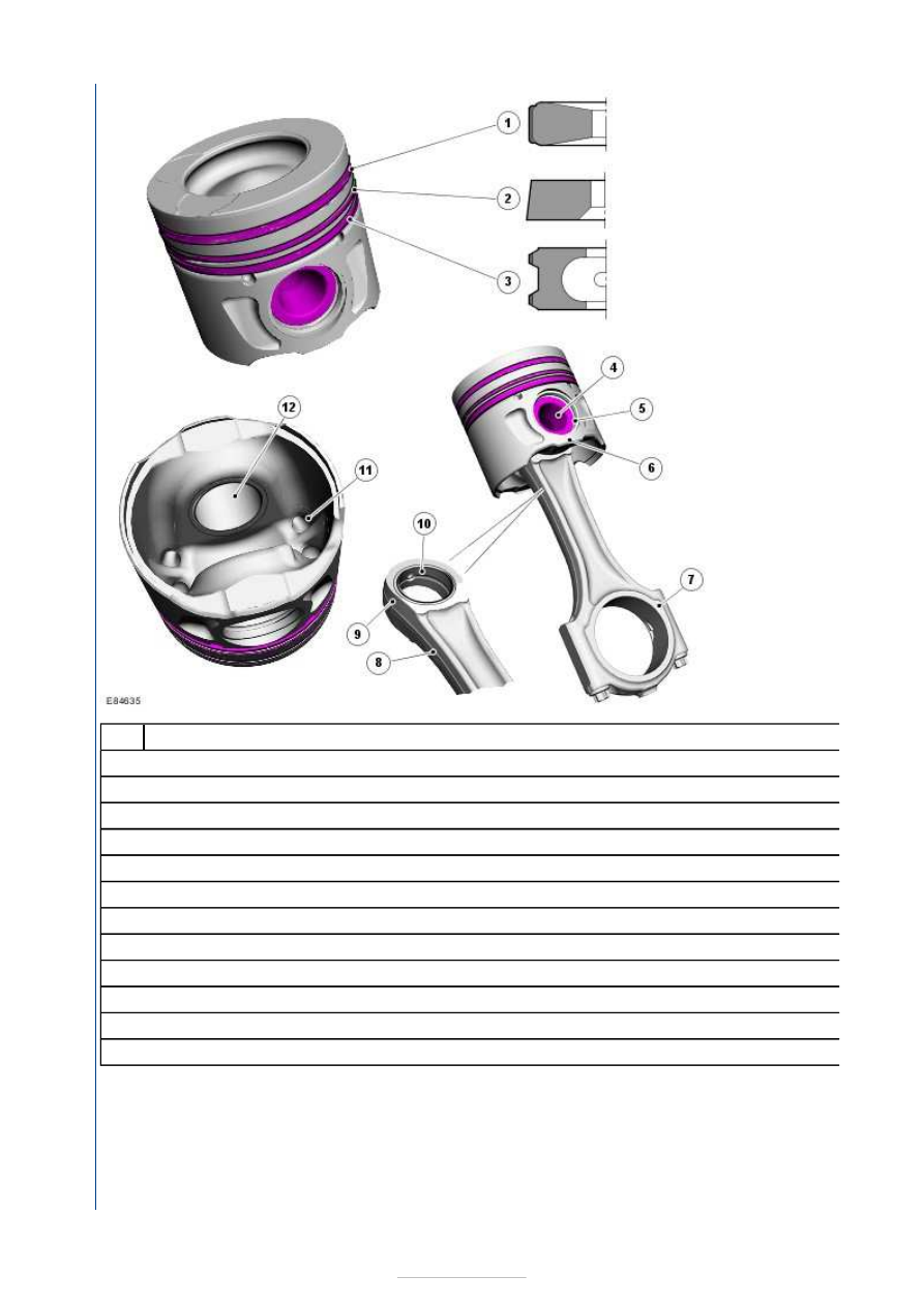
Description 

Upper compression ring 

Lower compression ring 

Oil control 'scraper' ring 

Gudgeon pin 

Gudgeon pin circlip (2 off) 

Piston and connecting rod assembly 

Connecting rod big-end 

Connecting rod shaft 

Connecting rod small-end 

Small-end bushing 

Piston crown cooling channel 

Piston bush (2 off per piston) 

Connecting rods 

The connecting rods are made from forged steel. 

The connecting rod small-end is narrowed on each side to form a tapered head. The taper improves the distribution of force 
between the piston and connecting rod during the combustion stroke. 

A bronze bush is installed in the small-end, and formed with an internal groove to allow the flow of lubricating oil around the 

Item

1

2

3

4

5

6

7

8

9

10

11

12


bush. 

Connecting rod big-end 

The connecting rod large end is split as a bearing housing. The bearing cap is mounted using two bolts.

The connecting rod size is engraved both on the connecting rod large end and on the bearing cap to denote that the 
components belong together. 

There is a bearing shell mounted in the connecting rod large end and in the bearing cap. 

The connecting rod large end, the bearing cap and the bearing shells have a lug that aligns the bearings in the housings and 
prevents radial movement of the bearing shells. During installation the lugs must face toward the LH side (oil filter side) of 
the engine. 

Pistons 

The pistons are made from an aluminium alloy and have a total of three piston rings. 

A steel insert is installed in the piston upper ring groove to provide reinforcement. 

A piston recess of typical design for direct diesel injection is incorporated into the piston crown.

Recesses are also formed in the piston crown to provide clearance for the 4 valve heads. This type of combustion chamber 
design produces optimum air/fuel mixture swirl. 

The 3 piston rings must be installed with the ring gaps spaced at 120° (with permissible tolerance of 15
other, around the piston. 

The 2 upper compression rings are stamped with 'top' to aid installation. 

The bearing surface of the piston is finished with a graphite substance for reducing friction in the cylinder bore.

Two oil cooling channels on the underside of the piston crown ensure optimum piston cooling. 

Balance shaft unit 


Description 

Propelled balance shaft (rotates counter to the crankshaft) 

Driven balance shaft 

Shims 

Balance shaft unit 

NOTE: The balance shaft unit must not be dismantled during servicing. 
NOTE: Before installing the balance shaft unit, the backlash between the two balance shafts
crankshaft and the driven balance shaft
 must be checked. 

The balance shaft unit contains two balance shafts and is arranged beneath the crankshaft. 

The assembly is attached with 8 bolts to the bottom of the cylinder block. 

The oil pump is arranged on the underside of the balance shaft housing (not illustrated). 

The balance shaft unit is attached to the cylinder block extension using two shims and eight bolts.

The backlash between the propelled balance shaft and the balance shaft drive gear at the crankshaft is determined using the 
shims. 

The balance shafts should counteract the different forces of inertia (caused by the countermovement of the piston pair) at 
the crankshaft. 

Operation 

Item

1

2

3

4


Description 

Front of the engine 

Direction of crankshaft 

Running direction of the driven balance shaft 

Running direction of the balance shaft propelled by the crankshaft 

Cylinder 1 piston 

Balance shaft drive gear 

The balance shaft drive gear at the crankshaft propels the propelled balance shaft in the opposite direction of rotation to the 
crankshaft. 

The driven balance shaft is propelled by the propelled balance shaft and rotates in the same direction as the crankshaft.

The balance shaft drive gear at the crankshaft has twice as many teeth as the mating gears on the two balance shafts. The 
gear ratio is therefore 1:2. 

Oil Pump Assembly 

Item

A

B

C

Drive

1

2


Content   ..  283  284  285  286   ..