Ford Galaxy / Ford S-MAX. Manual - part 283
 

  Index      Ford     Ford Galaxy / Ford S-MAX - service repair manual 2006 year


Search            


Content   ..  281  282  283  284   ..


Ford Galaxy / Ford S-MAX. Manual - part 283


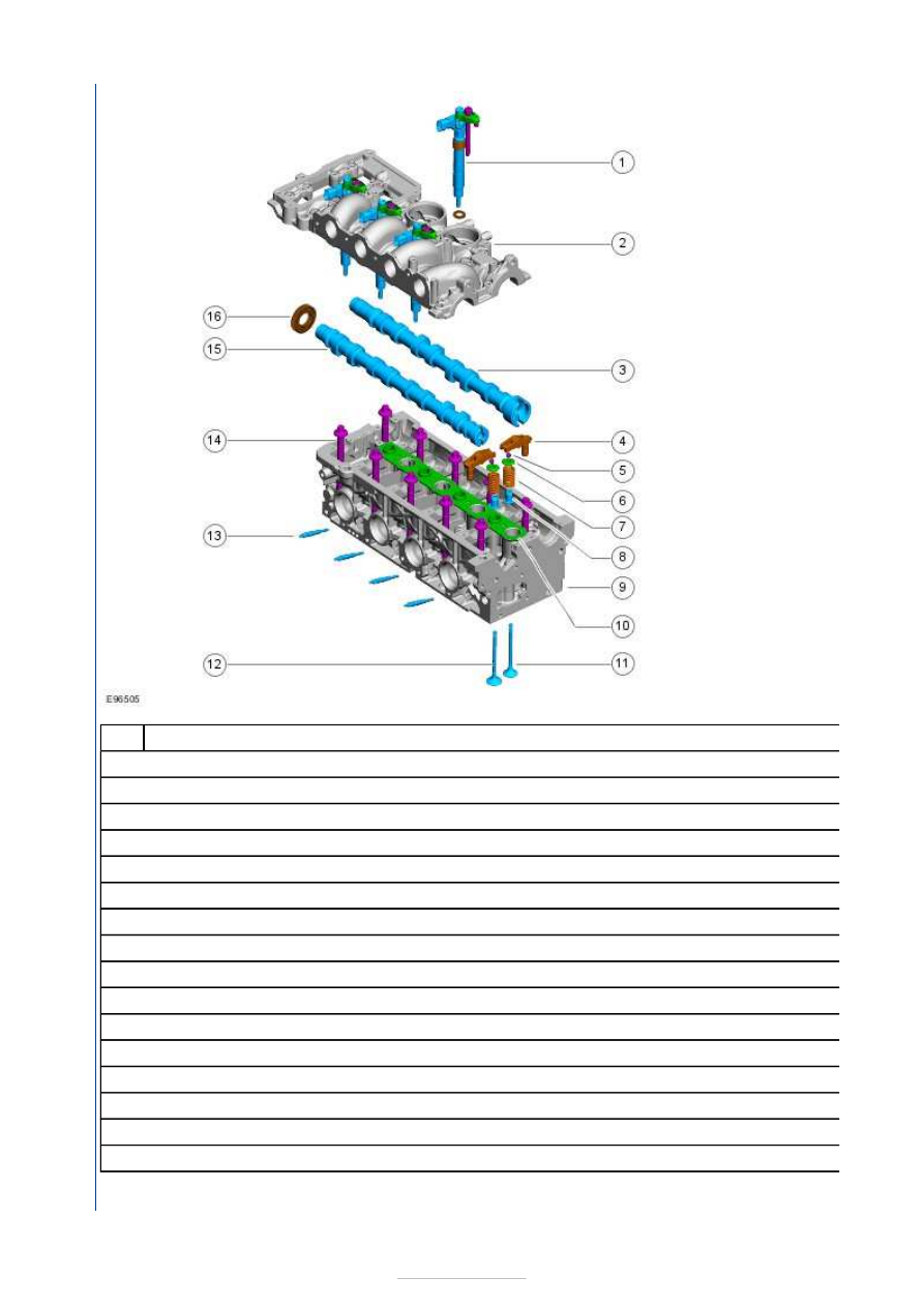
Description 

Fuel injector 

Cylinder head upper part 

Exhaust camshaft 

Roller tappet 

Valve collet 

Upper valve guide 

Valve spring 

Lower valve guide 

Cylinder head lower part 

Gasket 

Exhaust Valve 

Intake Valve 

Glow plug 

Cylinder head bolt (10 in total) 

intake camshaft 

Radial shaft seal of the front exhaust camshaft 

NOTE: The upper and lower parts of the cylinder head are matched to each other in terms of tolerances and must not be 

Item

1

2

3

4

5

6

7

8

9

10

11

12

13

14

15

16


renewed as individual parts. 
NOTE: The parts of the cylinder head must not be reworked. 

Both cylinder head parts have been matched to each other during production. Two guide sleeves position the cylinder head 
parts exactly. 

The upper part of the cylinder head is bolted to the lower part of the cylinder head and sealed as follows:

using silicon sealer (seals the outer area),  
using a ready-made gasket (seals the swirl ducts and the guides for the fuel injectors). 

The upper halves of the camshaft mountings are incorporated into the upper part of the cylinder head. The camshafts run 
directly in the aluminium. 

The camshafts are made from cast iron. The intake camshaft drives the vacuum pump at the rearward end. The exhaust 
camshaft drives the fuel pump at the rearward end. An O-ring provides the seal in each case. 

The lower part of the cylinder head is bolted to the cylinder block with a total of 10 bolts. The old cylinder head bolts may not 
be reused during servicing. 

Cylinder head gasket 


Description 

Cylinder head gasket thickness 

Cylinder head gasket thickness 

The multi-layer steel cylinder head gasket is available in four thicknesses depending on the piston protrusion.

Camshaft and camshaft drive 

Overview of the components 

Item

Connecting 

rod 

retaining 
bolts

b

Number of cut-outs

Piston protrusion

Cylinder head gasket thickness

1

0.55 - 0.60 mm

1.25 +/

2

0.61 - 0.65 mm

1.30 +/

3

0.66 - 0.70 mm

1.35 +/

4

0.71 - 0.75 mm

1.40 +/


Description 

Automatic timing belt tensioner 

Exhaust camshaft pulley 

Camshaft timing chain 

Exhaust camshaft sprocket 

Exhaust camshaft 

intake camshaft 

Intake camshaft sprocket 

Hydraulic timing chain tensioner 

Idler pulley 

Coolant pump drive gear 

Crankshaft timing belt pulley 

Timing belt 

Retaining bolt of the camshaft sprocket 

Washer 

Timing Cover 

Item

1

2

3

4

5

6

7

8

9

10

11

12

13

14


Description 

Rear timing cover 

Upper timing cover 

Lower timing cover 

Mounting bolt 

The plastic timing covers are secured to the engine using a total of nine bolts. 

There is a hole (arrow) in the upper timing cover. This hole permits the insertion of the special tool for securing the exhaust 
camshaft pulley. This allows fast checking of the valve timing. 

Camshaft Drive 


Description 

Camshaft pulley 

Exhaust camshaft 

intake camshaft 

Timing chain 

The exhaust camshaft is driven by the crankshaft via a timing belt. 

Item

1

2

3

4

Item

1

2

3

4


Content   ..  281  282  283  284   ..