Ford Galaxy / Ford S-MAX. Manual - part 192
 

  Index      Ford     Ford Galaxy / Ford S-MAX - service repair manual 2006 year


Search            


Content   ..  190  191  192  193   ..


Ford Galaxy / Ford S-MAX. Manual - part 192


The interior mechanism of the timing belt tensioner comprises a spring and a friction 
element. The friction element serves to absorb small vibrations and fluctuations in engine 
speed. The spring ensures the correct timing belt tension, regardless of wear and 
temperature. 

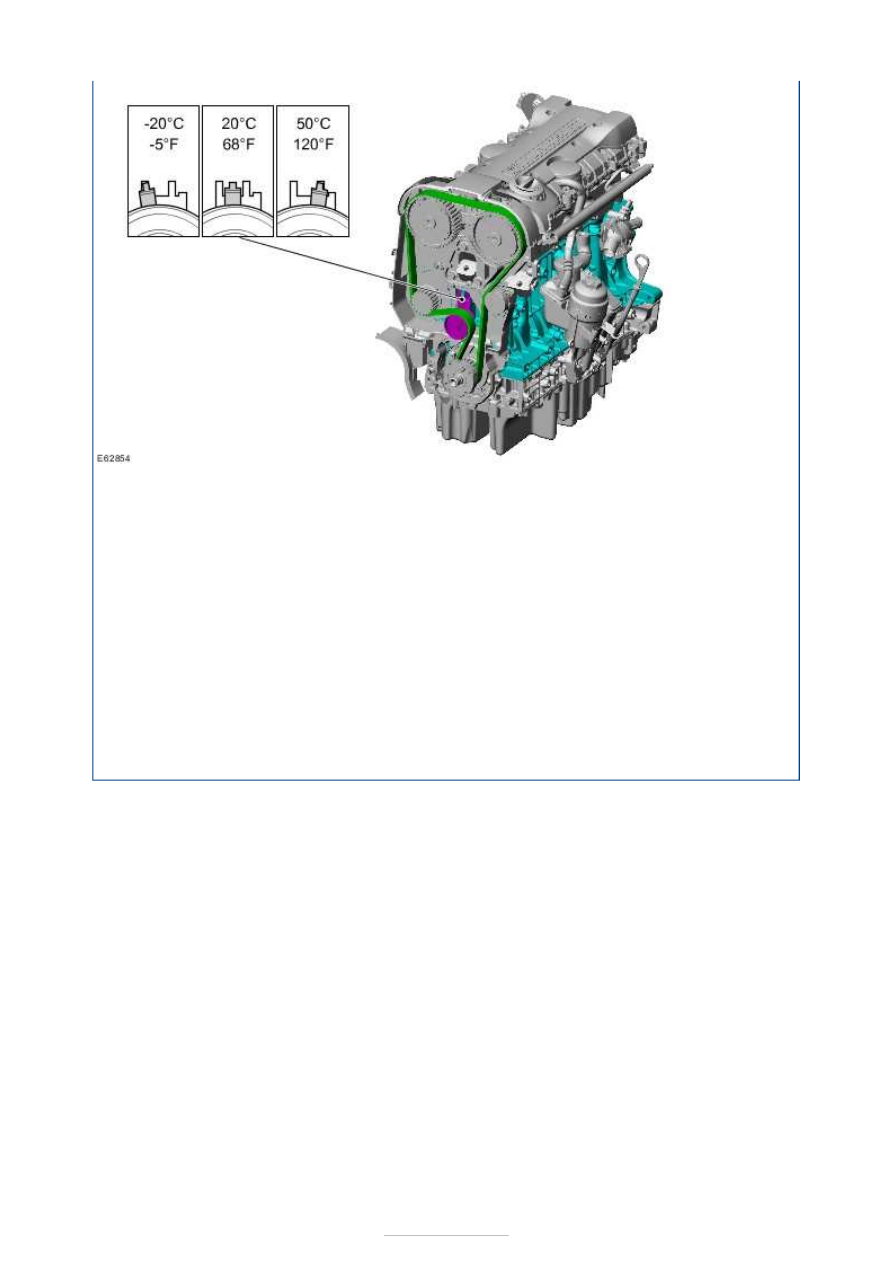
The tension of the timing belt should be set when the engine is cold. 

NOTE: If the engine temperature is higher or lower, remember that a different position is 
specified for the timing belt tensioner (see illustration). 

The timing belt should be fitted starting from the crankshaft over the idler pulley, the intake 
and exhaust camshaft pulleys, the coolant pump and finally on the timing belt tensioner. 

Once the timing belt has been correctly tensioned, the engine must be rotated by hand two 
turns clockwise at the crankshaft in order to allow a subsequent check of the timing belt 
tension and adjustment. 

No direction of movement is specified when using a new timing belt. If, however, the old 
timing belt is reused, the direction of movement must be marked prior to removal. 


Engine - 2.5L Duratec (162kW/220PS) - 
VI5 - Engine

S-MAX/Galaxy 2006.5 (02/2006-)


Print


Diagnosis and Testing 

General Equipment 

Materials 

Specification 

WSK-M2G349-A7  

Measure the compression pressure 

NOTE: The powertrain control module (PCM) receives an error message when the fuel 
pump relay is removed or electrical components are disconnected. This error message 
must be deleted from the fault memory using worldwide diagnostic system (WDS) after 
completing the compression test. 
NOTE: Valve clearance must be set correctly before performing a compression test. Run 
the engine to normal operating temperature. 
NOTE: The varying design of compression checking devices and fluctuating starter motor 
speeds normally only allows for a comparison to be made of the compression pressures in 
all cylinders. 

1. 1. Remove the central junction box (CJB) cover. 

2. 2. Open the CJB and remove fuse 22. 

3.

NOTE: The engine will start, run for a few seconds and then stop. 

3. Start the engine. 

4. 4. Disconnect the ignition coil-on-plug.  

REFER to: Zündspule - Direktzündung (303-07C, Removal and Installation). 

Worldwide Diagnostic System (WDS).

Name

Adhesive - Loctite 243


5. 5. Remove the spark plugs. 

NOTE: Operate the starter motor with wide open throttle until the reading on the 
compression tester stops rising. 

6. 6. Perform the measurement on each cylinder according to the instructions provided 

by the manufacturer of the measuring device. Use a compression pressure recorder 
with a suitable adapter. 

7. 7. Install the spark plugs. 

8. 8. Install the ignition coil-on-plug.  

REFER to: Zündspule - Direktzündung (303-07C, Removal and Installation). 

9. 9. Install fuse 22 and close the CJB. 


10. 10. Install the CJB cover. 

11. 11. Using 

worldwide diagnostic system (WDS)

, clear the fault codes from the 

powertrain control module (PCM). 

Measuring the oil pressure 

NOTE: The oil pressure is defined by several factors. Among others, this includes the 
engine speed, oil temperature, oil viscosity and the degree of filter contamination. 
NOTE: Measure the oil pressure at the specified engine speed. 

1. 1. Raise vehicle. REFER to: (100-02 Fahrzeug anheben)  

Anheben mit Wagenheber (Description and Operation), 
Anheben mit Hebebühne (Description and Operation). 

2. 2. Remove the engine under shield. 

3. 3. Disconnect the oil pressure switch electrical connector from the oil pressure switch. 


Content   ..  190  191  192  193   ..