Ford Galaxy / Ford S-MAX. Manual - part 191
 

  Index      Ford     Ford Galaxy / Ford S-MAX - service repair manual 2006 year


Search            


Content   ..  189  190  191  192   ..


Ford Galaxy / Ford S-MAX. Manual - part 191


Description 

Camshaft pulley 

Spring-loaded locking pin 

Rotor 

Rotor vane 

Plunger 

Return spring 

VCT oil control solenoid 

Duct connected to chamber (a) 

Duct connected to chamber (b) 

Oil feed duct 

Oil return duct 

When the VCT control unit is being advanced, the chamber (a) fills with engine oil. The 
rotor (3) starts to turn counter-clockwise as a result of the EOP prevailing in the chamber 
(a). This completes the advance adjustment. The engine oil returning from the chamber (b) 
flows via the oil return duct (D) to the VCT oil control solenoid and from there back into the 
oil pan. 

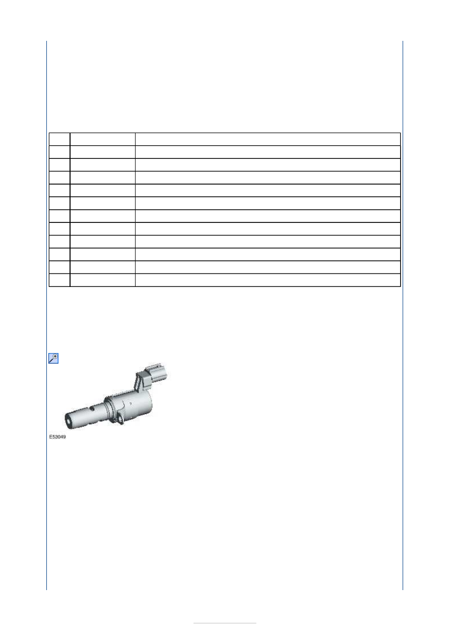
VCT oil control solenoid 

The VCT oil control solenoids are located in the front area in the centre on the valve cover. 
The purpose of the VCT oil control solenoids is to supply engine oil to the VCT control units 
in accordance with the actuation by the PCM. This causes the camshaft/valve timing to be 
either advanced or retarded. 

Cylinder block 

Item

1

2

3

4

5

6

7

A

B

C

D

Part Number

-

-

-

-

-

-

-

-

-

-

-


Description 

Cylinder block 

Ladder frame 

Oil pan 

The cylinder block consists of three parts. These are the cylinder block, ladder frame and oil 
pan. 

The cylinder block has five cylinder liners made of cast iron, which cannot be replaced. 

The ladder frame serves as a reinforcement and also forms the lower crankshaft bearings. 

The oil pan supports the sturdy construction and serves as an additional reinforcement. 

Crankshaft 

Item

1

2

3


Part Number

-

-

-


Description 

Crankshaft 

Timing belt pulley 

Cylindrical pin 

Timing belt pulley splines 

Wide spline 

Crankshaft outer splines 

Crankshaft inner splines 

The forged crankshaft in the 2.5L Duratec-ST (VI5) engine is supported in the cylinder 
block (upper crankshaft bearings) and in the ladder frame (lower crankshaft bearings) by 
six bearings. 

The shims are located at the 5th crankshaft main bearing. 

Located on the drive side of the crankshaft are two sets of splines. The inner splines drive 
the oil pump. The outer splines engage in the timing belt pulley. 

The timing belt pulley can only be pushed onto the outer shaft splines in one specific 
position. For this purpose, one spline on the timing belt pulley and one on the crankshaft 
have been made wider. 

The cylindrical pin secures the mass damper. 

Valve timing 

Item

1

2

3

4

5

6

7


Part Number

-

-

-

-

-

-

-

Timing marks 


Description 

Exhaust camshaft pulley timing mark 

Engine front cover with timing marks 

Intake camshaft pulley timing mark 

Intake camshaft pulley 

Exhaust camshaft pulley 

Crankshaft timing belt pulley timing mark 

Crankshaft timing belt pulley 

Crankshaft 

When checking the valve timing, ensure that the timing marks are aligned exactly. 

The front engine cover must always be installed when checking and adjusting the valve 
timing, i.e. timing belt tension, as the timing marks for both camshaft pulleys are provided 
on its front end. 

The mark on the crankshaft timing belt pulley must be in exact alignment with the mark on 
the oil pump housing. 

Timing belt tension 

Item

1

2

3

4

5

6

7

8


Part Number

-

-

-

-

-

-

-

-


Content   ..  189  190  191  192   ..