Ford Galaxy / Ford S-MAX. Manual - part 190
 

  Index      Ford     Ford Galaxy / Ford S-MAX - service repair manual 2006 year


Search            


Content   ..  188  189  190  191   ..


Ford Galaxy / Ford S-MAX. Manual - part 190


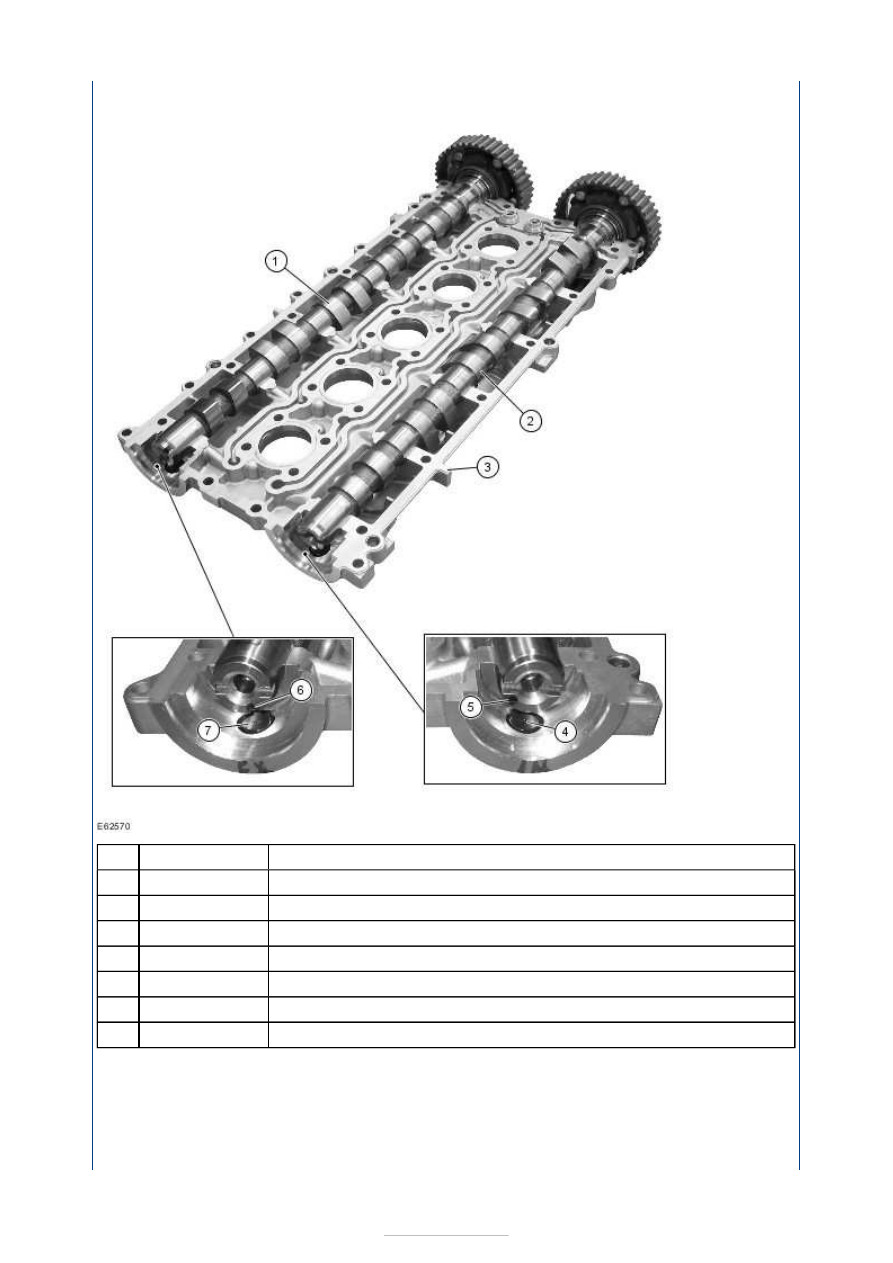
Description 

Exhaust camshaft 

Intake camshaft 

Valve cover / upper camshaft bearings 

CMP sensor for intake camshaft 

Intake camshaft reference mark 

Exhaust camshaft reference mark 

CMP sensor for exhaust camshaft 

Recesses are provided on the ends of the camshafts; these are for attaching the new 
special tool (Locking Tool, Camshaft 303-1183) for locking the camshafts. 

Threads have been cut into the camshafts for attaching the special tool (303-1178). 

NOTE: The new special tool (303-1178) can only be attached when the camshafts are 
precisely set to the timing marks. 

Item

1

2

3

4

5

6

7


Part Number

-

-

-

-

-

-

-

Refer to the workshop literature for the exact procedure for attaching and using the new 
special tool (303-1178). 

For detection of the CMP sensor signals, reference marks in the form of grooves have been 
machined into the ends of the camshafts. When the camshafts are set precisely to the 
timing marks, the machined mark on the exhaust camshaft is located roughly at the 5 
o'clock position and the machined mark on the intake camshaft is located at 8 o'clock. 

No marks have been provided on the camshafts in production; we therefore recommend 
marking the camshafts before removing them. 

Camshaft bearings 

Valve cover and cylinder head 


Description 

Camshaft bearings 

Valve cover 

Cylinder head 

Spark plug well sealing ring 

Exhaust camshaft 

Intake camshaft 

The camshafts are supported in the cylinder head (lower camshaft bearings) and in the 
valve cover (upper camshaft bearings) by six bearings. 

Item

1

2

3

4

5

6


Part Number

-

-

-

-

-

-

VCT (Variable Camshaft Timing) 

VCT control units 

The engine oil is pumped from the oil pan via the VCT oil control solenoids to the control 
units of the intake and exhaust camshaft as needed. Here, the camshaft timing is advanced 
or retarded, based on the input signals from the PCM. 

The VCT control units for the intake and exhaust camshafts are moved into the locked base 
position when the engine is stopped through the engagement of a spring-loaded locking 
pin. 

The movement to the locked base position is assisted by the tensile force of the timing belt 
for the intake VCT control unit. 

With the exhaust VCT control unit, a spring inside the control unit additionally assists in 
reaching the locked base position. 

The intake VCT control unit is in the "retarded timing" position and the exhaust VCT control 
unit is in the "advanced timing" position when in the locked base position. When the engine 
is started, the lock is hydraulically released when a certain EOP (Engine Oil Pressure) is 
reached. 

The procedures must therefore be strictly adhered to when performing adjustment work. 

The intake and exhaust VCT control units can only be replaced as complete units during 
servicing. 

Timing retard 


Description 

Camshaft pulley 

Spring-loaded locking pin 

Rotor 

Rotor vane 

Plunger 

Return spring 

VCT oil control solenoid 

Duct connected to chamber (a) 

Duct connected to chamber (b) 

Oil feed duct 

Oil return duct 

The engine oil is drawn from the oil pan and routed to the camshaft oil ducts via the engine 
oil circuit before being routed from there to the VCT oil control solenoid (7) and to the 
locking pin (2). This releases the locking pin (2) and separates the positive engagement 
between the camshaft pulley (1) and the rotor (3). When the control unit is being retarded, 
the chamber (b) fills with engine oil. The rotor (3) starts to turn clockwise as a result of the 
EOP prevailing in the chamber (b). The engine oil returning from the chamber (a) flows via 
the oil return duct (D) to the VCT oil control solenoid and from there back into the oil pan. 

Timing advance 

Item

1

2

3

4

5

6

7

A

B

C

D

Part Number

-

-

-

-

-

-

-

-

-

-

-


Content   ..  188  189  190  191   ..