Ford Galaxy / Ford S-MAX. Manual - part 1025


  Index      Ford     Ford Galaxy / Ford S-MAX - service repair manual 2006 year


Search            


Content   ..  1023  1024  1025  1026   ..


Ford Galaxy / Ford S-MAX. Manual - part 1025


reduce the movement of this mass accordingly (e.g. bumper on chassis). 

Damping affects the resonance of an object or system. 

Isolation 

In oscillation technology, the term isolation means decoupling (separation) of components 
and systems. An engine is mounted in sprung elements, so that as little oscillation as 
possible is passed to the vehicle. 

In automotive technology, the isolation technique used is nearly always rubber mounting. 
Rubber has a large internal damping capacity. The elasticity of the rubber acts like a spring. 

Absorption 

Sound waves are reflected from hard surfaces Through the use of absorption material, 
sound waves hit soft surfaces and are absorbed by them. 

The composition and thickness of the material used plays an important role here. A soft 
surface, depending on its composition, absorbs the sound waves and reduces their energy. 

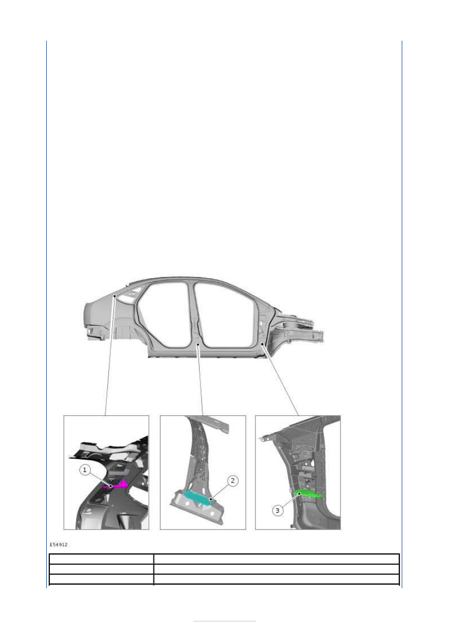
NVH elements 

NVH elements are installed to prevent airborne sound transfers to the passenger 
compartment in different body cavities. 

Item

Description

1

C-pillar area

2

B-pillar area


On the Focus 2004.75 (07/2004-) these elements are located in the cavities of the A, B and 
C pillars. On the estate version, they are also located in the D pillars. 

The NVH material consists of a carrier plate which has compressed isolation material at the 
edges. In the drying system of the painting equipment used in production, the body is 
heated to approx. 170° C. At this temperature the isolation material expands to seal the 
gap between the carrier plate and the bodywork. 

NOTE: NVH elements must not be damaged during work on the vehicle body. NVH 
elements deformed through impact must always be replaced. PU adhesive must always 
be applied to the edges of new and reused NVH elements during repair work. 

For the exact installation position of an NVH element, please refer to the vehicle-specific 
repair instructions. 

If an NVH element is to be reused, the bonding on the body panel must be detached. To do 
this, the body panel must be heated in the area around the NVH element. The bonding can 
be detached at approx. 170° C. The damaged panel part can now be carefully dismantled. 

Before installing the new panel part, a PU adhesive must be applied to the contact areas 
between the panel and the NVH element. 

Test techniques, measuring devices 

The shortest route to an accurate diagnosis results from: 

general information on the problem vehicle and a comparison test with a vehicle of the 
same construction, without NVH problems.  
vehicle history, including repair history and usage patterns.  
condition history, especially any relationship to repairs or sudden change.  
knowledge of probable causes.  
application of diagnosis procedures in which the vehicle is split into corresponding areas. 

The diagnosis and correction of noise, vibration and harshness concerns requires: 

general information on the problem vehicle and a comparison test with a vehicle of the 
same construction, without NVH problems.  
vehicle history, including repair history and usage patterns.  
condition history, especially any relationship to repairs or sudden change.  
knowledge of probable causes.  
application of diagnosis procedures in which the vehicle is split into corresponding areas. 

NOTE: The diagnosis of droning problems is one of the most difficult tasks in the NVH 
area. With the exception of installed components under stress, a certain diagnosis of 
droning problems (or boom) on customer vehicles makes great demands on the 
automotive technician. The performance of measuring equipment and their practice-

3

A-pillar area

Item

Description

1

NVH element

2

PU adhesive


orientated application can only be obtained through suitable instruction (NVH training). 
The successful use of these devices requires a great deal of experience on the part of the 
user.  

The diagnosis and correction of noise, vibration and harshness concerns requires: 

a road or system test to determine the exact nature of the concern. 

Analysis of possible causes: 

checking of the cause and elimination of the faults found.  
a road test or system test to make sure the concern has been corrected or brought back 
to within an acceptable range.  
It is often very difficult to locate noises that are audible in the passenger compartment 
based on the problem description provided by the customer and the road tests 
performed. The direction of the noise can be detected subjectively, but the source of the 
noise cannot be found. 

NOTE: For a selection of simple test tools, see the wind noises section. 

Electronic NVH tester 

NOTE: Before using the NVH tester in the service, the service technician should take part 
in an NVH training course to ensure effective use of this device during the road test. A 
description of the function and application of the NVH tester is enclosed with the device. 

The measuring device described below is used for diagnosis of the solid-borne sound and 
solid-borne sound transmission paths. The device is particularly suitable for medium and 
high frequency noise analyses. It principally enables noise diagnosis in the area of solid-
borne sound and helps to identify solid-borne sound transmission routes.  

In order to obtain a positive diagnosis of droning problems (low frequency noises) and their 
sources, you must have sufficient experience of how to use this measuring device. 

The device works according to the following operating principle: Accelerometers 
(transmitters) are fitted on various vehicle components or body areas. The signals recorded 
here can be listened to one after the other on headphones or speakers via the different 
channels. Simultaneous illustration of several or all measuring channels (for comparison) is 
only possible visually on the display of the measuring device. 

Layout and operation: 

The test device has six different channels for noise diagnosis.  
Each channel is marked in color on the terminal, cable and test device.  
The solid-borne sound recorded is transmitted to the test device or the headphones by 
the magnetic accelerometers (transmitters).  
There is an amplifier on the test device with which the signal strength and the 
corresponding channel can be set.  
Only the noises from a transmitter are transferred to the headphones.  
All connected cables can be visually illustrated individually or simultaneously on the 
display.  
The test device saves the recorded data.  


The recorded data can be imported to a PC and evaluated. 

The NVH tester is equipped in addition with mobile magnetic sensors which are particularly 
suitable for the following noise tests: 

Internal noises at the dashboard  
Engine noise  
Electrical noises (sparking/voltage transmissions)  
Wind noises  
Vacuum - leaks 

Chassis noise tester (chassis ear) 

Used to diagnose solid-borne sound and its transmission routes. The device is particularly 
suitable for medium and high frequency noise analysis and principally enables noise 
diagnosis in the area of solid-borne sound and helps to identify solid-borne sound 
transmission routes. 

In order to obtain a positive diagnosis of droning problems (low frequency noises) and their 
sources, you must have sufficient experience of how to use this measuring device. 

Layout and operation: 

The test device has six different channels for noise diagnosis. This means that six 
microphones equipped with clamps can be attached to different components on the vehicle. 
The emitted or transmitted solid-borne sound will be transferred from microphone to the 
headphones. There is an amplifier between the microphone and the headphones at which 
the signal strengths and the corresponding channel can be set. 

Only the noises from one microphone are transferred to the headphones. Each channel is 
color-coded on the clamp, cable and amplifier. 

NOTE: In order to be able to relate the positions of the different microphones during the 
test process, they are entered in a special test sheet according to their colors. 
Microphones, clamps and cables must be carefully routed and attached.  

Test process (example for transmission noise): 

Attach microphones to various positions on the transmission or mountings. This first 
allows the source of the noise to be determined, and then the possible transfer routes.  
A road test can be performed after all the clamps have been attached to the vehicle and 
all the cables connected to the amplifier.  
Firstly, all the channels are switched through one after the other in neutral, to check the 
operation of the different channels as well as the noise level in neutral.  
During the road test, all channels are listened to in the different gears, engine speeds, 
vehicle speeds and loads. This procedural method permits unambiguous diagnosis of the 
cause of the noise and the route of the noise until it enters the bodywork structure.  
The characteristics of the noise which is the cause of the concern should match those of 
the noise which is heard. This means compare the sound.  
Depending on the input signal level, there may be a great deal of difference in the noise 
level in the individual channels.  


Content   ..  1023  1024  1025  1026   ..