Ford Galaxy / Ford S-MAX. Manual - part 84
 

  Index      Ford     Ford Galaxy / Ford S-MAX - service repair manual 2006 year


Search            


Content   ..  82  83  84  85   ..


Ford Galaxy / Ford S-MAX. Manual - part 84


Installation 

1. Coat the O-rings on the refrigerant lines. 

Material: 

Compressor Oil - Air Conditioning (WSH-

M1C231-B / 6U7J-M1C231-AA)


2.

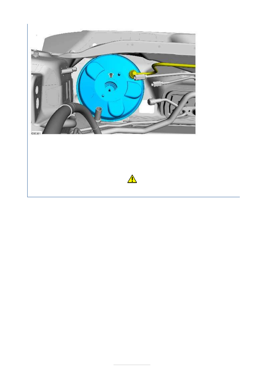
CAUTION: Make sure that the brake booster 

pushrod is correctly located. 

To install, reverse the removal procedure. 


Power Brake Actuation - Brake Vacuum 
Pump—2.5L Duratec (162kW/220PS) - 
VI5

S-MAX/Galaxy 2006.5 (02/2006-)


Print


Removal and Installation 

Removal 

NOTE: Removal steps in this procedure may contain installation details. 

Installation 

1. Torque: 10 Nm 

1. To install, reverse the removal procedure. 


Anti-Lock Control - Anti-Lock Control

S-MAX/Galaxy 2006.5 (02/2006-)


Print


Description and Operation 


Description 

Hydraulic control unit (HCU) 

Rear wheel speed sensors 

Front wheel speed sensors 

In addition to the conventional brake system with two diagonally split brake circuits, the 
anti-lock brake system (ABS) consists of an ABS hydraulic control unit with an integrated 
electronic control unit, four wheel speed sensors and the ABS warning indicator in the 
instrument cluster.  

Electronic brake force distribution software is integrated in the electronic control unit, which 
electronically regulates and optimizes the hydraulic pressure applied to the brake calipers 
on the front and rear axles in accordance with the operating conditions. 

Function 

The ABS is a closed loop control system which prevents the wheels from locking up under 
braking and therefore maintains steerability and driving stability in extreme situations 
within the physical limits.  

Item

1

2

3


Part Number

-

-

-

Anti-Lock Control - Anti-Lock Control

S-MAX/Galaxy 2006.5 (02/2006-)


Print


Diagnosis and Testing 

Refer to Wiring Diagrams Section 206-09A, for schematic and connector 
information.  

General Equipment 

Inspection and Verification 

1. 1. Verify the customer concern. 

2. 2. Visually inspect for obvious signs of mechanical or electrical damage. 

Visual Inspection Chart 

3. 3. If an obvious cause for an observed or reported concern is found, correct the cause 

(if possible) before proceeding to the next step. 

4. 4. If the cause is not visually evident, connect the diagnostic tool to the data link 

connector and select the vehicle to be tested from the diagnostic tool menu.  

Worldwide diagnostic system (WDS)

Mechanical

Electrical

Wheel speed sensor(s)  
Wheel speed sensor ring(s) 

Fuse(s)  
Electrical connector(s)  
Wiring harness(s). 


Content   ..  82  83  84  85   ..