Ford Galaxy / Ford S-MAX. Manual - part 73
 

  Index      Ford     Ford Galaxy / Ford S-MAX - service repair manual 2006 year


Search            


Content   ..  71  72  73  74   ..


Ford Galaxy / Ford S-MAX. Manual - part 73


side and the EPB module C4CB01 pin 29, circuit 
CCB17A (BU/GN), harness side 

Is the resistance greater than 10,000 ohms? 
Yes 

REPEAT the self-test, CLEAR the DTCs. If the DTC 
remains 

GO to U2

.  

No 

GO to U2

.  

U2: CHECK THE PARKING BRAKE RELEASE ACTUATOR CIRCUITS

Disconnect Parking Brake Release Actuator C4CB06. 

CAUTION: Make sure that the area around the 

component is clean and free of foreign material. 

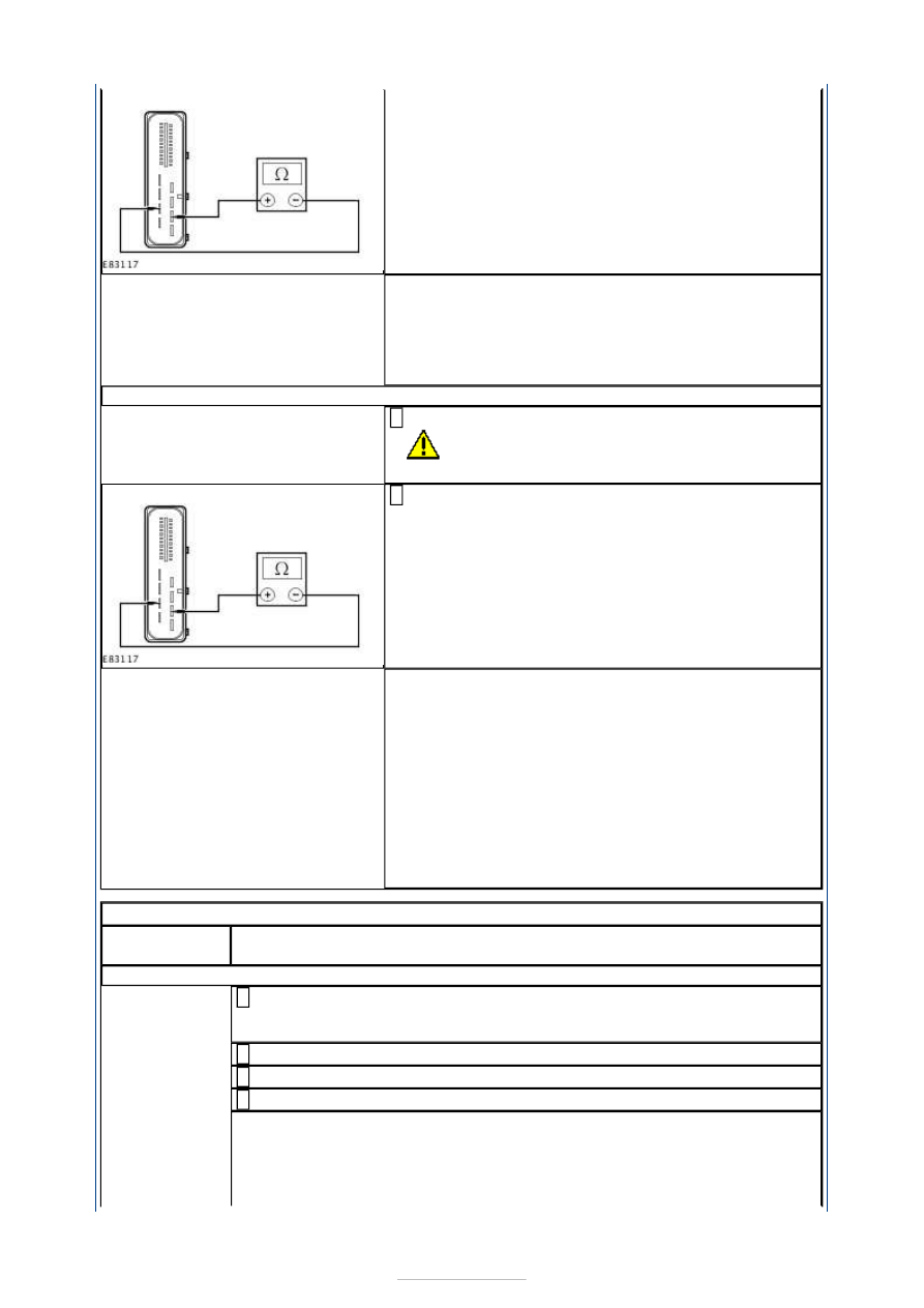
Measure the resistance between the EPB module 
C4CB01 pin 14, circuit CCB16B (WH/VT), harness 

side and the EPB module C4CB01 pin 29, circuit 
CCB17A (BU/GN), harness side 

Is the resistance greater than 10,000 ohms? 
Yes 

INSTALL a new parking brake release actuator.  
REFER to: Parking Brake Release Actuator (206-05 
Parking Brake and Actuation, Removal and 
Installation). 
REPEAT the self-test, CLEAR the DTCs. 

No 

REPAIR circuit CCB18A (YE/GY), or circuit CCB18B 
(YE/GY), or circuit CCB19A (GN/BN), or circuit 
CCB19B (GN/BN). REPEAT the self-test, CLEAR the 
DTCs. 

PINPOINT TEST V : DTC C2008.1D: LEFT ACTUATOR FAULT 

TEST 

CONDITIONS

DETAILS/RESULTS/ACTIONS

V1: CHECK THE BRAKE DISC AND PADS

Remove the wheel and tire.  
REFER to: Wheel and Tire (204-04 Wheels and Tires, Removal and 

Installation). 

Connect WDS. 

Select 'Service' mode and retract brake pads. 

CHECK the brake disc and brake pads. 

Are the brake disc and brake pads OK? 
Yes 

REFER to: Parking Brake Release Actuator (206-05 Parking Brake and 
Actuation, Removal and Installation). 

No 


REFER to: Brake Pads - Vehicles With: Electronic Parking Brake (206-04 
Rear Disc Brake, Removal and Installation). 

PINPOINT TEST W : DTC P061E: INTERNAL CONTROL MODULE BRAKE 
SIGNAL PERFORMANCE 

TEST CONDITIONS

DETAILS/RESULTS/ACTIONS

W1: CHECK THE WDS IS COMMUNICATING THROUGH THE DATA LINK CONNECTOR 
(DLC)

Ignition switch in position II. 

Select an alternative system to check the DLC. 

Is WDS able to communicate with the selected system? 
Yes 

GO to W2

.  

No 

CHECK the DLC. For additional information, REFER to 
the Wiring Diagrams. 

W2: CHECK THE POWERTRAIN CONTROL MODULE (PCM) CIRCUIT

Check for PCM DTCs. 

Is WDS able to communicate with the PCM? 
Yes 

CLEAR any PCM DTCs, REFER to WDS, then 

GO to 

W3

.  

No 

CHECK the PCM circuits.  
REFER to: 

Communications Network

 (418-00 Module 

Communications Network, Diagnosis and Testing). 

W3: CHECK THE ABS MODULE CIRCUIT

Check for ABS DTCs. 

Is WDS able to communicate with the ABS module? 
Yes 

CLEAR any ABS DTCs, REFER to WDS, then 

GO to 

W4

.  

No 

REPAIR circuit VDB04S (WH/BU) or circuit VDB05S 
(WH). REPEAT the self-test, CLEAR the DTCs. 

W4: CHECK THE CJB

Check for CJB DTCs. 

Is WDS able to communicate with the CJB? 
Yes 

CLEAR any CJB DTCs, REFER to WDS, then 

GO to W5

No 

REPAIR circuit VDB04Y (WH/BU) or circuit VDB05AB 
(WH). REPEAT the self-test, CLEAR the DTCs. 

W5: CHECK THE EPB MODULE CIRCUIT

Is WDS able to communicate with the EPB module? 
Yes 

GO to W6

.  

No 

REPAIR circuit VDB04N (WH/BU) or circuit VDB05E 
(WH). REPEAT the self-test, CLEAR the DTCs. 

W6: CHECK THE CENTRAL JUNCTION BOX (CJB) CIRCUIT

Disconnect EPB Module C4CB01. 

Disconnect CJB C1BP02-C. 

Measure the resistance between the: 

EPB module C4CB01 pin 16, circuit VDB04N 

(WH/BU), harness side and the CJB C1BP02-C pin 
47, circuit VDB04Y (WH/BU), harness side.  
EPB module C4CB01 pin 17, circuit VDB05E (WH), 
harness side and the CJB C1BP02-C pin 48, circuit 
VDB05AB (WH), harness side. 

Are the resistances less than 5 ohms? 
Yes 

REPEAT the self-test, CLEAR the DTCs. 

No 

REPAIR circuit VDB04Y (WH/BU) or circuit VDB05AB 
(WH). REPEAT the self-test, CLEAR the DTCs. 

PINPOINT TEST X : DTC U0001: HIGH SPEED CAN BUS 

TEST CONDITIONS

DETAILS/RESULTS/ACTIONS

X1: CHECK THE CAN BUS FOR A SHORT CIRCUIT

Disconnect EPB Module C4CB01. 

Measure the resistance between the EPB module 
C4CB01 pin 16, circuit VDB04N (WH/BU), harness 

side and the EPB module C4CB01 pin 17, circuit 
VDB05E (WH), harness side. 

Is the resistance less than 5 ohms? 
Yes 

REPAIR circuit VDB04N (WH/BU) or circuit VDB05E 
(WH). REPEAT the self-test, CLEAR the DTCs. 

No 

GO to X2

.  

X2: CHECK THE CAN HIGH BUS CIRCUIT FOR A SHORT TO GROUND

Measure the resistance between the EPB module 
C4CB01 pin 16, circuit VDB04N (WH/BU), harness 

side and ground. 

Is the resistance less than 5 ohms? 
Yes 

REPAIR circuit VDB04N (WH/BU). REPEAT the self-
test, CLEAR the DTCs. 

No 

GO to X3

.  

X3: CHECK THE CAN LOW BUS CIRCUIT FOR A SHORT TO POWER

Ignition switch in position II. 

Measure the voltage between the EPB module 
C4CB01 pin 17, circuit VDB05E (WH), harness side 

and ground. 


Is any voltage present? 
Yes 

REPAIR circuit VDB05E (WH). REPEAT the self-test, 
CLEAR the DTCs. 

No 

GO to X4

.  

X4: CHECK THE CAN BUS CIRCUIT CONTINUITY

Ignition switch in position 0. 

Measure the resistance between the: 

EPB module C4CB01 pin 16, circuit VDB04N 
(WH/BU), harness side and the DLC C3DB04 pin 6, 
circuit VDB04L (WH/BU), harness side.  
EPB module C4CB01 pin 17, circuit VDB05E (WH), 
harness side and the DLC C3DB04 pin 14, circuit 
VDB05Z (WH), harness side. 

Are the resistances less than 5 ohms? 
Yes 

INSTALL a new EPB module.  
REFER to: Parking Brake Module (206-05 Parking 
Brake and Actuation, Removal and Installation). 
REPEAT the self-test, CLEAR the DTCs. 

No 

REPAIR circuit VDB04N (WH/BU) or circuit VDB05E 
(WH). REPEAT the self-test, CLEAR the DTCs. 

PINPOINT TEST Y : DTC U2002.62/92: EPB SWITCH FAULT 

TEST CONDITIONS

DETAILS/RESULTS/ACTIONS

Y1: CHECK THE EPB SWITCH CIRCUITS FOR A SHORT TO POWER

Disconnect EPB Module C4CB01. 

Disconnect EPB Switch C3CB09. 

Ignition switch in position II. 

Measure the voltage between the: 

EPB module C4CB01 pin 9, circuit CCB23A 
(VT/GN), harness side and ground.  
EPB module C4CB01 pin 10, circuit CCB25A (BN), 
harness side and ground.  
EPB module C4CB01 pin 11, circuit CCB21A 
(GN/VT), harness side and ground.  
EPB module C4CB01 pin 18, circuit CCB22A 
(WH/BN), harness side and ground.  
EPB module C4CB01 pin 19, circuit CCB24A 
(WH/OG), harness side and ground.  
EPB module C4CB01 pin 20, circuit CCB20A 
(BU/WH), harness side and ground. 


Content   ..  71  72  73  74   ..