Ford Galaxy / Ford S-MAX. Manual - part 49
 

  Index      Ford     Ford Galaxy / Ford S-MAX - service repair manual 2006 year


Search            


Content   ..  47  48  49  50   ..


Ford Galaxy / Ford S-MAX. Manual - part 49


During a blow-out, very rapid tire pressure is experienced. The tire pressure monitoring 
system is not intended to warn the driver of a blow-out, since it is not possible to give the 
driver sufficient warning that such an event is occurring, due to its short duration. The 
design of the tire pressure monitoring system is to assist the driver in keeping the tires at 
the correct pressure, which may reduce the likelihood of a tire blow-out occurring. 

Principles of Operation 

On driving off at a speed of more than 20 kph (12.5 mph) the central junction box (CJB) 
sends a low-frequency (LF) signal to each tire pressure monitoring system antenna in turn. 
Each antenna initiates its specific tire low pressure sensor. The corresponding tire low 
pressure sensor responds after detecting its LF signal by sending a radio frequency (RF) 
(315 MHz or 433 MHz depending on market) signal. These signals contain data which 
corresponds to tire low pressure sensor identification, tire pressure, tire temperature and 
vehicle acceleration information. 

As each wheel responds to the LF signal from the CJB, it is assigned a position on the 
vehicle and is monitored for the remainder of that drive cycle in that position. 

The tire pressure monitoring system antennas operate in turn for 15 seconds in the 
following order: 

Left-hand front  
Right-hand front  
Right-hand rear  
Left-hand rear 

Each tire low pressure sensor responds in turn so that the CJB can establish the tire low 
pressure sensor positions at the start of the drive cycle. This process is repeated up to 3 
times but less if the tire low pressure sensor positions are already known in the CJB. This 
process takes 3 to 4 minutes to complete. During this period the tire low pressure sensors 
transmit at regular intervals once every 15 seconds. For the remainder of the drive cycle 
the tire low pressure sensors transmit once every 60 seconds or if a change in tire pressure 
is sensed until the vehicle stops and the tire pressure monitoring system returns to park 
mode. 

The low tire pressure warning occurs at 25% + 35% deflation and consists of amber and 
red warning lamp indicators and an appropriate message displayed in the information and 
message center. The information and message center will also display additional 
information about the position of the affected tire(s). 

The tire pressure monitoring system enters the park mode after the vehicle speed has been 
less than 20 km/h (12.5 mph) for 15 minutes. In park mode the tire low pressure sensors 
transmit a coded signal to the CJB once every 13 hours. If the tire pressure decreases by 
more than 0.06 bar (1 lbf/in²) within the 13 hours, the tire low pressure sensor will 
transmit more often as the tire pressure is lost. 

Tire Low Pressure Sensor 

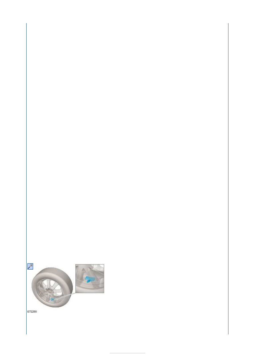
The tire pressure monitoring system uses active tire low pressure sensors which are 
mounted on each wheel, inside the tire cavity. The tire low pressure sensor is retained in 
position by the tire valve nut to the wheel. The tire low pressure sensors transmit their RF 


signals at either 315 MHz or 433 MHz dependent on market requirements. 

The tire low pressure sensors periodically measure the tire pressure and temperature of the 
air inside the respective tires. Pressure and temperature measurements are transmitted 
periodically to the RF receiver on the vehicle. 

The tire low pressure sensors are self-contained units. 

The safety points detailed in tire changing must be followed to avoid damage to the tire low 
pressure sensor. If the tire low pressure sensor is removed, the nut, valve core, cap, seal 
and washer must also be installed and the tire low pressure sensor tightened to the correct 
torque value. 

It is strongly recommended that the valve seal and steel washer is replaced each time a tire 
is changed to avoid a seal failure. The seal and washer must be replaced if the sensor is 
removed. Removal of the sensor retaining nut must be regarded as sensor removal. The 
valve cap must always be in place except when inflating, releasing pressure or checking 
pressure. 

The RF transmission from the tire low pressure sensor contains a unique identification code 
in its transmission data so that the CJB can identify the tire on the vehicle. If a new tire low 
pressure sensor is installed on a road wheel, the new tire low pressure sensor identification 
will be learnt when the vehicle is first driven at a speed of more than 20 km/h (12.5 mph) 
for 15 minutes.  

It is strongly recommended that the valve seal and steel washer is replaced each time a tire 
is changed to avoid a seal failure. The seal and washer must be replaced if the sensor is 
removed. Removal of the sensor retaining nut must be regarded as sensor removal. The 
valve cap must always be in place except when inflating, releasing pressure or checking 
pressure. 

Tire Pressure Monitoring System Antenna(s) 

The tire pressure monitoring system has four tire pressure monitoring system antennas. 
The tire pressure monitoring front antennas are located on top of the fender splash shield. 
The tire pressure monitoring rear antennas are located on the rear bumper bracket. Each 
tire pressure monitoring system antenna has a connector which connects with the body 
wiring harness. 

The tire pressure monitoring antenna is a passive, LF transmitter. Each tire pressure 
monitoring system antenna is controlled by the CJB and provides an auto-location feature 
to identify tire positions on the vehicle. 

The CJB energizes each tire pressure monitoring antenna in turn using LF drivers. The 
corresponding tire low pressure sensor detects the resulting LF transmission and modifies 
the mode status within the RF transmission. This data is received by the CJB through the 
RF receiver. The CJB can then determine which tire low pressure sensor is transmitting and 
its location on the vehicle. 

CJB 


The function of the CJB with the tire pressure monitoring system is to detect the following: 

The tire pressure is below the recommended low tolerance value – under-inflated tire  
The position of the tire on the vehicle. 

The CJB communicates with the vehicle instrument cluster to provide the driver with 
appropriate warnings and also indicates the status/failure of tire pressure monitoring 
system components. 

Tire Location 

Because of the requirement for different pressure targets and thresholds for the front and 
rear tires, the CJB needs to identify the position of the tires on the vehicle and assign a 
received tire low pressure sensor identification to a specific position on the vehicle (left-
hand front (FL), right-hand front (FR), left-hand rear (RL) or right-hand rear (RR)). 

Tire location is carried out automatically by the CJB using an auto-location function. The 
CJB automatically learns the position of tires on the vehicle if the tire low pressure sensors 
or their positions are changed on the vehicle. 

The CJB automatically detects, under normal conditions, the following: 

One or more new tire low pressure sensors have been installed  
One or more tire low pressure sensor has stopped transmitting  
Signals from tire low pressure sensors that do not belong to the vehicle. 

RF receiver 

The RF receiver is part of the central locking system and is located above the headliner in 
the vicinity of the overhead console. 

The RF receiver receives tire pressure, temperature and vehicle acceleration information 
from each tire low pressure sensor and interfaces with the CJB. The CJB then transmits the 
appropriate messages to the instrument cluster through the controller area network (CAN) 
bus. 

The RF receiver also receives further information from each tire low pressure sensor 
concerning wheel identification, mode status and the condition of the tire low pressure 
sensor. 

Instrument Cluster 


The tire pressures on all 4 tires are displayed in the message center of the instrument 
cluster, after being relayed by the CJB. Warnings are also visually displayed by the amber 
and red warning indicators and a message is displayed in the information and message 
center. 

The warning indicators are driven by CAN messages from the CJB. 

Tire Pressure Monitoring System Load Setting 

The tire pressure monitoring system load setting switch is used by the driver to set the 
required load conditions of the vehicle, normal load or high load. 

Using the button located on the steering wheel right-hand side switch, select the 
Information/Tires menu (located in the instrument cluster information and message 
center). 

To set the tire pressure monitoring system load setting required, select Set up/Tires menu. 

The tire pressure monitoring system load setting can now be selected:  

· Low load 

· High load 

To confirm the setting select OK. 


Content   ..  47  48  49  50   ..