Ford Galaxy / Ford S-MAX. Manual - part 43
Description
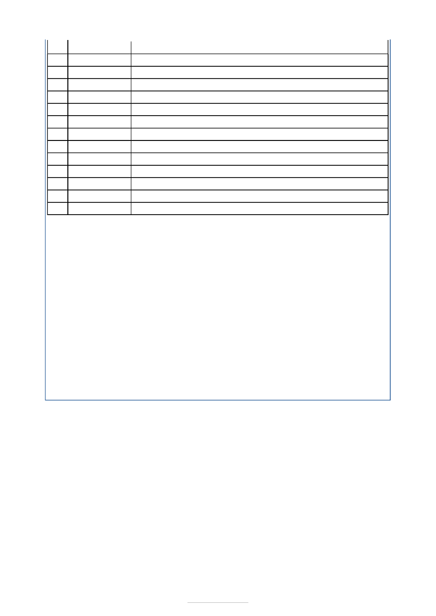
Continuous damping control shock absorber
Upper arm
Spring seat
Rear subframe
Rear lower arm adjustment cam nut
Stabilizer bar, bushings and clamps
Bump stop
Spring and spring upper pad
Rear lower arm and spring lower pad
Stabilizer bar link
Front lower arm
Wheel knuckle
Wheel hub
Item 1: Shock Absorber
Continuous damping control shock absorbers (if equipped) provide dynamic front
suspension. A continuous damping control shock absorber creates a damping force which
depends on the velocity of the vehicle and an electrical current applied to the continuous
damping control shock absorber. The electronic stability program (ESP) sensors,
acceleration sensors and displacement sensors provide information to the dynamic
suspension electronic control unit (ECU), which detects the state of heave, roll, pitch,
cornering and acceleration of the vehicle. The ECU then calculates the best damping
characteristics for each wheel within 2 ms. The ECU sends an individual electrical current to
each shock absorber to control the amount of damping required.
Item 2: Upper Arm
The upper arm is a different shape to the standard suspension upper arm to allow clearance
of the shock absorber.
Item 10 : Stabilizer Bar Link
The stabilizer bar link is a combination link. This consists of a solid link attached to the
stabilizer bar with a retaining nut and a ball joint link attached to the wheel knuckle with a
retaining nut. The ball joint link provides a quicker response to suspension movement. This
enables the stabilizer bar to respond more directly to wheelstation movement.
Item
1
2
3
4
5
6
7
8
9
10
11
12
13
Part Number
-
-
-
-
-
-
-
-
-
-
-
-
-