Ford Falcon. Manual - part 204
303-14-30
Powertrain Control Management
303-14-30
DESCRIPTION AND OPERATION (Continued)
4-8
Ω @20º C.
Connections
3. Reconnect the HEGO harness and start the
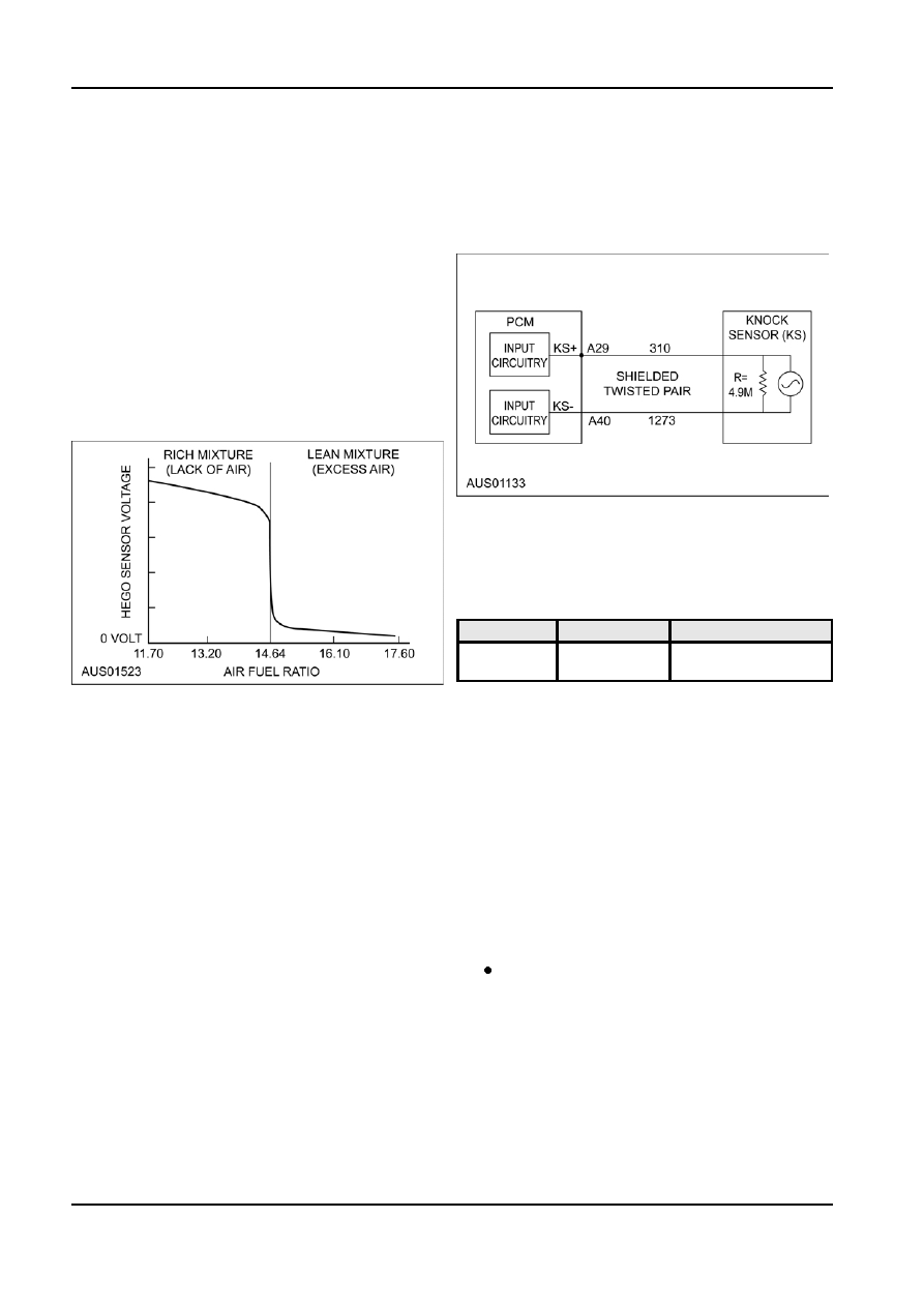
PCM Pin A29.......................Knock Sensor Positive
engine. With the throttle held open to maintain
PCM Pin A40.......................Knock Sensor Negative
approximately 2,000 RPM, The HEGO voltage
should be switching between High and Low at
Circuit
least once per second; and the rich/lean periods
should be reasonably even. If this does not occur
and the voltage remains constant, either High or
Low, open and close the throttle rapidly and look
for a change in voltage. If the voltage changes
with throttle movement, it indicates that the sensor
is operating correctly but the PCM, is not able to
control the air-fuel ratio.
4. Check the harness for open circuits and short
circuits.
HEGO Sensor Signal Voltage Specification
Diagnosis
Diagnostic Trouble Codes (DTC) are retrieved through
the diagnostic connector using the WDS tester.
DTC applicable to the KS sensor is shown in the
following table.
DTC
Test Mode
Condition
P0325
Cont.
Sensor or circuit
malfunction
Failure Mode
Knock Sensor
Should the KS fail, or produce the incorrect signal, the
Sensor Description
PCM will log a fault code, then revert to minimum
Vehicles fitted with the I6 engine have a linear Knock
ignition advance. The vehicle will otherwise operate
Sensor (KS) located on the left hand side of the
as normal, possibly with marginally less performance,
cylinder block, adjacent to cylinder No. 5 to detect
and some engine knock may occur under certain
pre-ignition detonation (engine knock) within the
conditions.
cylinders. The system detects engine knock by
Testing
comparing engine noise at crank angles when
cylinder pressure of the combustion fuel is highest
Testing Knock Sensor
with engine noise at quieter portions of the engine
1. Disconnect the knock sensor wire connector.
cycle. If the noise is louder, indicating knock, the
2. Measure the resistance across the knock sensor
Powertrain Control Module (PCM) retards ignition
connector terminals using a suitable multimeter.
timing until knocking ceases.
Replace the sensor if not within specification.
The KS is used as a feed-back signal to control
KS Resistance Specification
ignition timing. The KS is a piezo-electric
4 - 6 m
Ω
accelerometer comprised of a piezo crystal mounted
3. Check the harness for open circuits and short
in a ceramic case. Whenever the KS detects knock
circuits.
the PCM retards the ignition timing until the knock
ceases. The PCM then advances the ignition timing in
Feed Forward Inputs
small increments until knock is again detected. The
cycle of retarding and advancing the ignition is
Transmission Range Sensor (TRS-A1)
continuous in Closed Loop Mode, and maintains the
ignition at the optimum spark advance for the fuel
The automatic Transmission Range Sensor A1
quality.
(TRS-A1) <PRNDL>, is incorporated in the inhibitor
switch mounted on the side of the transmission case.
The PCM uses the KS to automatically adjust the
The TRS-A1 sensor reports the current gear lever
engine tune for low octane unleaded fuel or higher
performance Premium unleaded fuel.
G98129 en