Ford Falcon. Manual - part 205
303-14-34
Powertrain Control Management
303-14-34
DESCRIPTION AND OPERATION (Continued)
2. Where ABS and traction control is fitted, ensure
Circuit
that the warning lights are not illuminated. Rectify
before continuing.
3. Connect a WDS tester to the diagnostic
connector.
4. Check the check the Output Shaft Speed and the
Vehicle Speed on the WDS screen. If these reads
0, check the electrical connections between the
PCM and the vehicle speed source.
5. If vehicle speed is inaccurate, reconfigure the
PCM VID block as detailed in the Module
Configuration section.
PID Specification
PID
Description
AXLE
Axle Ratio used by the PCM
Diagnosis
TIRE SIZE
Tire size used by the PCM - revs
DTCs applicable to this sensor are shown on the
per mile
following table.
Vehicle Speed Output (VSOUT)
DTC
Test Mode
Condition
The PCM transmits a 12V square wave vehicle speed
P2122
KOEO Cont
PPS1 fails - Out-of-range
output signal on the VSOUT pin for the satellite
low
navigation system. This pin may be used to drive
P2123
KOEO Cont
PPS1 fails - Out-of-range
other devices such as taximeters. The recommended
high
load for this pin is 4.7 to 15 k
Ω to ground.
P2124
KOEO Cont
PPS1 fails - intermittent,
Connections
Out-of-range
P2138
KOEO Cont
PPS1 fails - In-range
PCM Pin B7
…………………………………. VSOUT
P2139
(one sensor disagrees)
Electronic Throttle Control Inputs
P2127
KOEO Cont
PPS2 fails - Out-of-range
low
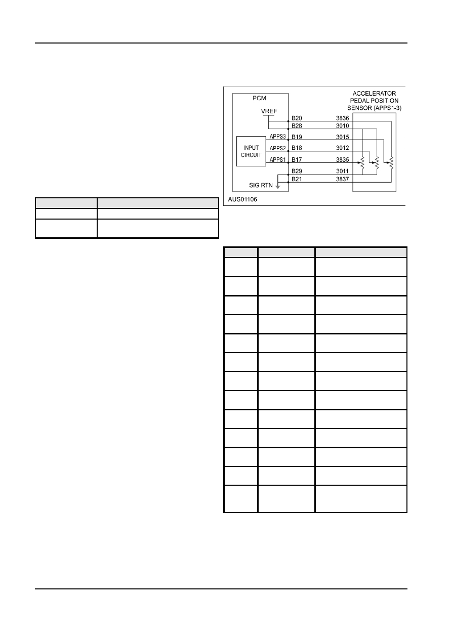
Pedal Position Sensor
P2128
KOEO Cont
PPS2 fails - Out-of-range
A triple output Throttle Position Sensor (TPS) is used
high
to provide pedal position signal to the PCM. It has an
P2129
KOEO Cont
PPS2 fails - intermittent,
8-way electrical connector providing 3 independent
Out-of-range
potentiometer signals.
P2138
KOEO Cont
PPS2 fails - In-range
P2140
(one sensor disagrees)
Connections
P2132
KOEO Cont
PPS3 fails - Out-of-range
PCM Pin B17
………….……………… PPS1 Signal
low
PCM Pin B18
………….……………… PPS2 Signal
P2133
KOEO Cont
PPS3 fails - Out-of-range
PCM Pin B19
………….……………… PPS3 Signal
high
PCM Pin B20
………….…………..…… PPSVREF1
P2134
KOEO Cont
PPS3 fails - intermittent,
PCM Pin B28
………….…………….…. PPSVREF2
Out-of-range
PCM Pin B21
…………………………….PPSRTN1
P2139
KOEO Cont
PPS3 fails - In-range
P2140
(one sensor disagrees)
PCM Pin B29
……………………………. PPSRTN2
P2110
KOEO Cont
Two or three PPS fail
(pedal position > or = no
pedal)
Failure Mode
The Failure Mode Effects Management (FMEM)
strategy will, in most cases, ensure normal operation
of the vehicle if one of the PPS potentiometers fail.
The ETC warning light will flash. If two or more
sensors fail, the ETC will default to limp home part
G98130 en